1. Introduction
Bar-wrapped cylinder concrete pressure pipe (BCCP) is a new type of large diameter composite pipeline and initially appeared in China in 2015. BCCP originated from traditional prestressed concrete cylinder pipe (PCCP), which has been in use for over 70 years in the United States. Several problems occur during the PCCP application process. One of the most serious problems is that the hydrogen embrittlement in prestressed steel wires often leads to the burst of pipe (Nuernberger 2009; Romer et al. 2007)
| [16] | Nuernberger, U. (2009). "Reasons and prevention of corrosion-induced failures of prestressing steel in concrete." International Journal of Structural Engineering, 1(1), 29-39. |
| [17] | Romer, A., Bell, G., Clark, B., and Ellison, D. (2007). "Failure of Prestressed Concrete Cylinder Pipe." Proc., International Conference on Pipeline Engineering and Construction, Boston, Massachusetts, United States, 1-17. https://doi.org/10.1061/40934(252)64 |
[16, 17]
. To solve the problem, BCCP was designed and manufactured. In 2016, BCCP was applied to the renewal of China Yanhuanding Pumping Project to adapt the high causticity environment and approximately 70 km long pipelines were replaced. The design, manufacturing standards and installation of BCCP refer to the AWWA C304 Design of Prestressed Concrete Cylinder Pipe (AWWA 2007) and AWWA M9 Concrete Pressure Pipe (AWWA 2008)
| [1] | AWWA (American Water Works Association) (2007). "Standard for Design of Prestressed Concrete Cylinder Pipe." AWWA C304, Denver, CO. |
| [2] | AWWA (American Water Works Association) (2008). "Concrete Pressure Pipe." AWWA MANUAL M9, Denver, CO. |
[1, 2]
.
BCCP consists of four main parts, including a concrete core, a steel cylinder, prestressing wires and an outer protective layer, similar to the components in PCCP. Instead of high tensile prestressing wires, cold rolled ribbed bars are used as the prestressing wires to avoid the hydrogen embrittlement due to its high stress strength. Hydrogen embrittlement can lead to the brittle fracture of prestressing wires, resulting in the loss of prestress. In addition, fiber reinforced fine aggregate concrete replaces mortar as the outer protective layer in BCCP, because the prestressing wires can be corroded due to the low strength and high permeability of the mortar coating layer in PCCP, while the fiber reinforced fine aggregate concrete protective layer has higher strength, crack-resistance ability, impermeability and appearance quality than mortar coating layer (Kayali et al. 2003)
| [10] | Kayali, O., Haque, M. N., and Zhu, B. (2003). "Some characteristics of high strength fiber reinforced lightweight aggregate concrete." Cement and Concrete Composites, 25(2), 207-213. https://doi.org/10.1016/S0958-9465(02)00016-1 |
[10]
. BCCP diameters reach from 500 mm through 2600 mm and can work under no more than 2 MPa internal pressure.
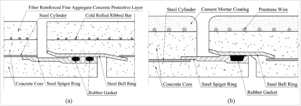
Both BCCP and PCCP have two types of construction: lined type and embedded type. The steel cylinder is lined with the concrete core in the lined type or embedded in the concrete core in the embedded type. The joint structures of BCCP (embedded type) and PCCP (embedded type) are shown in
Figure 1. Joints in BCCP consist of a steel spigot ring, two rubber gaskets and a steel bell ring. The steel spigot ring is welded with steel cylinder in the spigot end of the pipe and the steel bell ring is welded with steel cylinder in the bell end. The gaskets are used for the seal between rings and provide longitudinal friction to avoid excessive longitudinal movement. After pipes field assembly, grout is placed on the exterior joint recess to protect the steel joint rings from corrosion. Double-gasketed joints in BCCP have a convenience in the pressure test of joints and the water-tightness of these is also better than single-gasketed joints in PCCP.
Figure 1. Schematic of the joints in (a) BCCP; (b) PCCP.
The foundation conditions in long-distance water transmission lines are always complicated. In some special construction sections, BCCP may pass through soft soil foundation that is mainly composed of silt and clay. When climate changes or the foundation is under nonuniform external load, differential settlements of foundation may occur due to its high compressibility and low strength, resulting in the excessive relative rotation angle between pipes (Gould et al. 2009; Wols et al. 2014)
| [7] | Gould, S., Boulaire, F., Marlow, D., and Kodikara, J. (2009). "Understanding how the Australian climate can affect pipe failure." Proc., Ozwater 09, Melbourne Convention & Exhibition Centre, Melbourne, Australia. |
| [20] | Wols, B. A., van Daal, K., and van Thienen, P. (2014). "Effects of Climate Change on Drinking Water Distribution Network Integrity: Predicting Pipe Failure Resulting from Differential Soil Settlement." Procedia Engineering, 70, 1726-1734. https://doi.org/10.1016/j.proeng.2014.02.190 |
[7, 20]
. The rigid contact between the rings leads to the phenomenon of stress concentration in joints, which makes the joints become the weakest part in the whole pipe system. When there is relative rotation angle between two pipes, the level of pressure transmitted by joints depends on the angle magnitude. At large angles, steel spigot ring and steel bell ring have great large deformation and transmit force to other components of joint structures, whose strength is far lower than steel rings, especially the interface layer between concrete and steel cylinder.
Recently, many experimental and numerical methods have been used to evaluate the whole structure performance of pipes under complex loading or with broken wires (Bardakjian and Murphy 2013
| [3] | Bardakjian, H., and Murphy, M. (2013). "Development History and Characteristics of the Bar-Wrapped Concrete Cylinder Pipe." Proc., Pipelines 2013, Fort Worth, Texas, United States, 340-349. https://doi.org/10.1061/9780784413012.032 |
[3]
; Zarghamee 2003
| [23] | Zarghamee, M. S. (2003). "Hydrostatic pressure testing of prestressed concrete cylinder pipe with broken wires." Proc., Pipeline Engineering and Construction International Conference 2003, Baltimore, Maryland, United States, 294-303. https://doi.org/10.1061/40690(2003)19 |
[23]
; Zarghamee et al. 2003
| [24] | Zarghamee, M. S., Eggers, D. W., Ojdrovic, R., and Rose, B. (2003). "Risk Analysis of Prestressed Concrete Cylinder Pipe with Broken Wires." Proc., Pipeline Engineering and Construction International Conference 2003, Baltimore, Maryland, United States, 599-609. https://doi.org/10.1061/40690(2003)81 |
[24]
). Some studies also focus on calculating the deformation of pipe bodies due to foundation settlements (Kouretzis et al. 2014)
| [11] | Kouretzis, G. P., Karamitros, D. K., and Sloan, S. W. (2014). "Analysis of buried pipelines subjected to ground surface settlement and heave." Canadian Geotechnical Journal, 52(8), 1058-1071. https://doi.org/10.1139/cgj-2014-0332 |
[11]
and examining the water-tightness of different pipe joint types (Bardakjian 2004; Hajali et al. 2016)
| [4] | Bardakjian, H. H. (2004). "A High Pressure Bar-Wrapped Concrete Cylinder Pipeline with Double-Gasketed Steel Joints." Proc., Pipeline Division Specialty Congress, San Diego, California, United States, 1-10. https://doi.org/10.1061/40745(146)84 |
| [8] | Hajali, M., Alavinasab, A., and Shdid, C. A. (2016). "Structural performance of buried prestressed concrete cylinder pipes with harnessed joints interaction using numerical modeling." Tunnelling and Underground Space Technology, 51, 11-19. https://doi.org/10.1016/j.tust.2015.10.016 |
[4, 8]
. García et al. (García et al. 2019) considered that a tandem axle configuration of RC pipeline can produce larger joint rotation using a numerical model with a gasketed bell and spigot joint
| [6] | García, D. B., Moore, I. D., and Cortés-Pérez, J. (2019). "Modeling and Parametric Study of Gasketed Bell and Spigot Joint in Buried RC Pipeline." Journal of Pipeline Systems Engineering and Practice, 10(3), 04019015. https://doi.org/10.1061/(ASCE)PS.1949-1204.0000383 |
[6]
. But few studies have been devoted to study relationships between the failure of joints and relative rotation angles under different working conditions. Therefore, the objective of this study is to investigate the mechanical properties of joint structures in BCCP under different relative rotation angles based on experimental and numerical method, including stress distribution and failure modes in joints. Several factors are also considered in numerical model to explore the effects of structure changes on the joint failure.
2. Experimental Details
Two BCCP pipes were manufactured to conduct rotation test, simulating the relative rotation of pipes due to foundation settlements. The pipes relative rotation angle and strain state in the joints were continuously monitored during the test. The type of these pipes was DN1400, whose parameters are shown in
Table 1.
Table 1. Parameters of BCCP.
Pipe type | Length [mm] | Inner diameter [mm] | Outer diameter [mm] | Steel cylinder diameter [mm] | Concrete core thickness [mm] | Steel cylinder thickness [mm] | Concrete protective layer thickness [mm] |
DN1400 | 6000 | 1400 | 1740 | 1500 | 110 | 2 | 60 |
DN1600 | 6000 | 1600 | 1980 | 1700 | 130 | 2 | 60 |
DN1800 | 6000 | 1800 | 2180 | 1900 | 130 | 2 | 60 |
DN2000 | 6000 | 2000 | 2480 | 2100 | 180 | 2 | 60 |
2.1. Experimental Setup
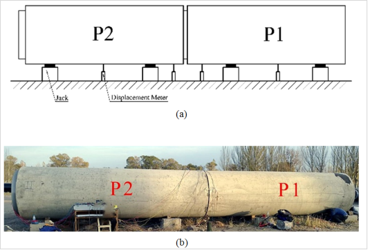
Figure 2 show the pipe rotation test, where two pipes (P1 and P2) were installed above the ground. The relative rotation angle between two pipes was changed by four jacks placed under pipes and four displacement meters were used to measure displacement in different positions of pipes. Three types of loading modes were designed to test the structure performance of joints under different loading conditions: the height of P1’s bell end decreases in loading mode 1, the height of P1’s spigot end decreases in loading mode 2 and the height of both P1’s bell end and spigot end decrease in loading mode 3.
Figure 2. (a) Schematic of experimental setup; (b) Testing field.
2.2. Data Collection and Processing
All the displacement and strain data were collected simultaneously by DH3816 static date acquisition instrument at different relative rotation angles. The clearance between bell end and spigot end in top and bottom of joints were measured by vernier caliper at beginning and end of the test.
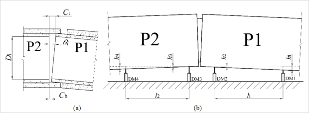
Assume that the angle of the pipe rotating clockwise is positive, and the angle of the pipe rotating anticlockwise is negative, as shown in
Figure 3(a). The initial relative rotation angle,
, is calculated from Eq. (
1).
Where
is the inner diameter of joints,
is the clearance between bell and spigot in top of inner concrete core, and
is the clearance between bell and spigot in bottom of inner concrete core. The total relative rotation angle,
, is calculated from Eq. (
2).
Where
is the change of relative rotation angle during the test that can be calculated from Eq. (
3).
(3)
Where
,
,
and
are the displacement value measured by the displacement meter 1 (DM1), DM2, DM3 and DM4, respectively. Assume that the displacement value is positive when the height of pipe decreases, and the displacement value is negative when the height of pipe increases.
is the horizontal distance between DM1 and DM2,
is the horizontal distance between DM3 and DM4, as shown in
Figure 3(b).
Figure 3. (a) Clearance between joints; (b) The placement of displacement meters.
3. Numerical Method
Considering the complex structures and interactions in the joints, finite element method (FEM) was used to analyze the strain-stress state of joint structures, implemented in the ABAQUS program. In this paper, the numerical model of pipes, especially joint structures, was established to investigate the mechanical properties of joints and compare the results with the rotation test.
3.1. Nonlinear Finite Element Model
A three-dimensional model of two DN1400 BCCP pipes, whose parameters are shown in
Table 1, was created in ABAQUS/Standard. Cold rolled ribbed bars are 10 mm in diameter and wrap around the concrete core with a pitch of 23 mm. A zero-thickness interface layer was placed between steel cylinder and concrete core to determine if there would be interfacial debonding in joint structures. The rubber gaskets were not included in the model due to its flexibility and lower stress, which have a little influence on the distribution of stress around the joints (Najafi et al. 2012)
| [15] | Najafi, M., Ramirez, G., Mielke, R., Keil, B., Davidenko, G., Rahman, S., Jain, A., and Practice (2012). "Design, analysis, and full-scale testing of the rolled groove gasket joint system in AWWA C303 bar-wrapped, steel-cylinder concrete pressure pipe." Journal of Pipeline Systems Engineering, 4(3), 156-169. https://doi.org/10.1061/(ASCE)PS.1949-1204.0000133 |
[15]
.
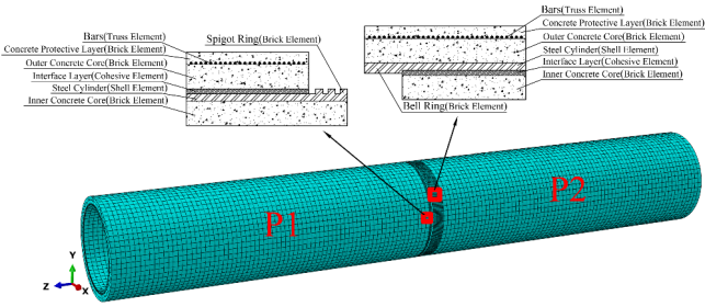
Four different types of elements were adopted according to the shapes of pipe components, as shown in
Figure 4. An 8-node 3D linear brick element (C3D8) was applied in modeling the concrete layer and joint rings. A 4-node doubly curved general-purpose shell element (S4) was applied in modeling the steel cylinder. A 2-node 3D linear truss element (T3D2) was applied in modeling cold rolled ribbed bars. A zero-thickness 8-node 3D cohesive element (COH3D8) created by node projection method was applied in modeling the interface layer. The cohesive elements are connected to the adjacent concrete and cylinder by sharing nodes with them. Cohesive elements are capable of simulating fracture in the bonded interface whose aspect radio is very small using a traction-separation law. Fine mesh finite elements were used in joint steel rings and concrete core to achieve higher accuracy simulating results around joints.
Interaction between steel rings and concrete was tie constraint and bars were embedded in the outer concrete core. Contact between P1’s spigot ring and P2’s bell ring was modeled using surface-to-surface contact whose property was defined by two parameters: hard contact in normal behavior and a friction formulation based on penalty with a friction coefficient of 0.15 in tangential behavior. Moreover, two static analysis steps were created to simulate applying prestress process (Step 1) and loading process (Step 2). In Step 1, two pipes’ protective layer elements were deactivated, and both spigot ring and bell ring were fixed. In Step 2, two pipes’ protective layer elements were reactivated, and boundary conditions were changed according to the loading modes that were consistent with the rotation test. In loading mode 1, P1’s spigot end and P2’s spigot end were fixed, and a vertical displacement load of 80 mm was applied to the P1’s bell end. In loading mode 2, P1’s bell end and P2’s spigot end were fixed, and a vertical displacement load of 60 mm was applied to the P1’s spigot end. In loading mode 3, only P2’s spigot end was fixed, a vertical displacement load of 60 mm was applied to the P1’s spigot end and a vertical displacement load of 80 mm was applied to the P1’s bell end. The gravity load of 9.8 m/s2 was applied to the whole FEM model in the two analysis steps.
Cooling method was used to simulate applying prestress to the bars by decreasing temperature in bar elements. The prestress value can be controlled flexibly depending on the prestress loss value, by adjusting temperature values in different regions of the bars, the temperature decreasing value,
, is calculated from Eq. (
4).
Where is prestress loss coefficient, is the gross wrapping stress in bars that is equal to 72% of its tensile strength in BCCP, is the linear expansion coefficient of bars that is taken as 1.0x10⁻⁵/°C, and is the Young’s Modulus of bars.
The limit relative rotation angle is determined when failure occurs in one of the joint components or the component reaches its ultimate strength. Due to the assembly clearance between bell ring and spigot ring, there can be free relative rotation angle between two pipes. The theoretical limit free relative rotation angle,
, is calculated from Eq. (
5).
Where
is the assembly clearance,
is the insertion depth when the P1’s spigot is pushed into the P2’s bell end. After that, coercive relative rotation angle begins to emerge as the relative rotation angle increasing, and the total limit relative rotation angle,
, can be calculated from Eq. (
6).
Where is limit coercive relative rotation angle. Assume that there is no assembly clearance in the FEM model, the total limit relative rotation angle is equal to the limit coercive relative rotation angle obtained from this model. Several factors that influence the limit relative rotation angle were also considered in the FEM model, such as prestress loss, insertion depth, loading modes, pipe types and inner water pressure.
Figure 4. Finite element mesh model of a whole model and element types.
3.2. Material Parameters
The designed concrete grade of concrete core and concrete protective layer were 50 and they were modeled with a uniaxial compression strength,
, of 32.4 MPa and a uniaxial tension strength,
, of 2.64 MPa. The density, Young’s modulus and Poisson’s ratio of the BCCP components used in the FEM model are shown in
Table 2.
Table 2. Material parameters of BCCP components.
Component | Density [kg/m3] | Young’s modulus [GPa] | Poisson’s ratio |
Concrete core, Concrete protective layer | 2500 | 34.5 | 0.2 |
Cold rolled ribbed bar | 7850 | 190 | 0.3 |
Steel cylinder, Steel ring | 7830 | 210 | 0.274 |
3.2.1. Material Modeling of Concrete
Concrete damaged plasticity model (CDPM) was used in this paper to simulate mechanical response of concrete under complex loading. CDPM in ABAQUS is defined by four major components: yield criterion, plastic flow rule, hardening/softening law and damage evolution.
Yield criterion defines the shape of yield surface, beyond which materials enter in the plastic state. Yield function adopted in CDPM was firstly presented by Lubliner et al. (Lubliner et al. 1989) and then revised by Lee and Fenves (Lee and Fenves 1998) and it is in the form of Eq. (
7)
| [12] | Lee, J., and Fenves, G. L. (1998). "Plastic-Damage Model for Cyclic Loading of Concrete Structures." Journal of Engineering Mechanics, 124(8), 892-900. https://doi.org/10.1061/(ASCE)0733-9399(1998)124:8(892) |
| [13] | Lubliner, J., Oliver, J., Oller, S., and Oñate, E. (1989). "A plastic-damage model for concrete." International Journal of Solids and Structures, 25(3), 299-326. https://doi.org/10.1016/0020-7683(89)90050-4 |
[12, 13]
.
(7)
Where
is the Mises equivalent effective stress,
is the effective hydrostatic stress,
is the first invariant of effective stress tensor,
is the second invariant of deviatoric effective stress tensor,
is maximum principal effective stress, the Macauley bracket
is defined as
. The parameter
,
and
are given in Eq. (
8).
The value of the ratio of biaxial compressive strength to uniaxial compressive strength,
, is 1.16, according to (Systèmes 2014)
| [18] | Systèmes, D. (2014). ABAQUS 6.14 Analysis User’s Guide, Providence, RI. |
[18]
.
is the radio of the tensile to the compressive meridian that determines the shape of the deviatoric trace and the default value is 0.667 in (Systèmes 2014)
| [18] | Systèmes, D. (2014). ABAQUS 6.14 Analysis User’s Guide, Providence, RI. |
[18]
.
and
are the effective tensile and compressive cohesion stresses, respectively.
The hardening/softening law can be obtained from uniaxial compressive/tensile stress-strain relationship of concrete. The uniaxial compressive stress-strain relationship is in the form of Eq. (
9), according to the code GB 50010-2010 (2015 Edition) (MOHURD 2015)
| [14] | MOHURD (Ministry of House and Urban-Rural Development of People’s Republic of China) (2015). "Code for design of concrete structures." GB50010-2010(2015 Edition), Beijing, China. |
[14]
.
(9)
Where the value of concrete compressive strain corresponding to uniaxial compressive strength,
, is equal to 1.678x10⁻³ and the parameters
,
,
, are adopted in this model for concrete C50.
is the concrete initial elastic modulus, which is given in
Table 2.
Damage parameter, d, is introduced in CDPM to describe the stiffness degrading in compression () and in tension () after the liner-elastic range, and it is defined as
where
,
and
are the concrete stress, total strain and plastic strain, respectively. According to (Xu et al. 2014)
, concrete compressive damage and tension damage are close related to the inelastic strain and cracking strain, respectively. The damage evolution adopted in this paper is in the form of Eq. (
11-12), according to (Wang and Chen 2006)
| [19] | Wang, J., and Chen, Y. (2006). Applications of ABAQUS in civil engineering, China: Press of Zhejiang University. Publication No. C2118999F, Zhejiang, China. |
[19]
.
(11)
(12)
Where the normalized parameters,
and
. For plain concrete, the value of ultimate inelastic strain,
, and ultimate cracking strain,
are 0.033 and 0.0033, respectively, and the parameters
,
are recommended (Huang and Liew 2015)
| [9] | Huang, Z., and Liew, J. Y. R. (2015). "Nonlinear finite element modelling and parametric study of curved steel–concrete–steel double skin composite panels infilled with ultra-lightweight cement composite." Construction and Building Materials, 95, 922-938. https://doi.org/10.1016/j.conbuildmat.2015.07.134 |
[9]
. Furthermore, according to (Chi et al. 2017)
| [5] | Chi, Y., Yu, M., Huang, L., and Xu, L. (2017). "Finite element modeling of steel-polypropylene hybrid fiber reinforced concrete using modified concrete damaged plasticity." Engineering Structures, 148, 23-35. https://doi.org/10.1016/j.engstruct.2017.06.039 |
[5]
, the concrete damage initiates after reaching the peak of
or
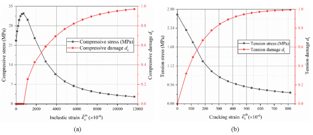
. Finally, the relationships between compressive stress and inelastic strain, compressive damage and inelastic strain, tension stress and cracking strain, tension damage and cracking strain, as shown in
Figure 5, are imported into the tabular forms in ABAQUS.
Figure 5. Concrete damage evolution curve: (a) compression; (b) tension.
3.2.2. Material Modeling of Steel Components
Elastic isotropic and perfectly plastic model was used in this paper to describe the material properties of cold rolled ribbed bar, steel cylinder and steel rings. This model assumes that the material stress-strain relationship is linear up to its yield strength, and after that the stress remains unchanged with the increase of strain.
Where
,
,
and
are the material stress, strain, elastic modulus and yield strength, respectively. The elastic modulus of cold rolled ribbed bar, steel cylinder and steel rings are given in
Table 2. The yield strength of cold rolled ribbed bar is 585 MPa and the ultimate strength of it is 650 MPa. The steel cylinder and steel rings are made of structural steel, whose yield strength is 235 MPa. In this paper, it is additionally supposed that metal material is up to its limit state when the material reaches its yield strength.
3.2.3. Material Modeling of Interface Layer
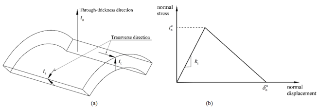
A traction-separation law was appropriate for the definition of cohesive element constitutive response because the thickness of interface layer between the steel and concrete is negligibly small. The nominal traction stress vector,
, in the 3D cohesive element consists of three components: the normal (through-thickness direction) component,
, and the two transverse components,
and
, as shown in
Figure 6(a). As is known, BCCP’s longitudinal length and hoop length are much longer than radial length. It is reasonable to assumed that only radial debonding can occur in joint structures, in other words, only the magnitude of normal component determines the bonding state while ignoring the influence of transverse component.
The initial behavior of this constitutive model is linear elastic and the initiation and evolution of damage follow the linear elastic region. In this paper, it is assumed that the failure of interface layer begins at the initiation of damage. Maximum nominal stress criterion is used to define the damage initiation. When the maximum nominal normal stress ratio reaches a value of one, as , damage begins to emerge, where corresponds to the peak nominal normal stress. The Macauley bracket means that no damage emerges when the interface layer is under a pure compressive deformation.
Displacement-based linear softening equation is adopted in this model to define the damage evolution. Thus the traction-separation constitutive response of interface layer is determined by three parameters:
, the slope of linear elastic region,
, the peak nominal normal stress and
, the ultimate normal displacement, as shown in
Figure 6(b). The parameters
,
and
for the interface layer between inner concrete core and steel cylinder. These parameters can be measured from concrete-steel plate normal bonding properties experiments.
Figure 6. (a) The nominal traction stress vector in the cohesive element; (b) The traction-separation constitutive response of the cohesive element.
4. Results and Discussion
Three failure indicators are considered to evaluate the pipe joint mechanical properties under different relative rotation angles, including: the debonding of the interface layer, the cracking of concrete, and yielding of the steel ring. CDPM assumes that the cracking of concrete initiates when the maximum principal plastic strain is positive, and the orientation of cracks is perpendicular to the direction of the maximum principal plastic strain. Moreover, it is supposed in this paper that the joint structures are up to its carrying capacity limit state when the steel rings begin to yield. So, the whole failure process of joint structures can be divided into four stages, which will be illustrated in this section. The effects of prestress loss, insertion depth, loading modes, pipe types and inner water pressure on the limit values corresponding to different failure stages are also discussed in this section.
4.1. Different Stages in the Whole Failure Process
From the results of experimental and numerical methods, the failure of joint structures mainly occurs in three components of the joint structures, including the interface layer, the spigot end inner concrete core and the steel spigot ring. Thus, four stages of failure are the debonding of P2’s bell end interface layer, the cracking of P1’s spigot end inner concrete core, the debonding of P1’s spigot end interface layer and the yielding of P1’s steel spigot ring, respectively, arranged in the order of failure occurrence, which are the typical failure mode of the DN1400 joint structures in loading mode 1 without prestress loss and inner water pressure. Due to the limitations and safety consideration of the experiment, only failure stage 2 can be monitored by the experimental method while the whole failure process can be observed in FEM results.
4.1.1. Failure Stage 1: The Debonding of P2’s Bell End Interface Layer
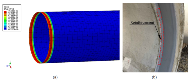
In step 1, when the applying prestress is up to 49% of the gross wrapping stress in bars, the interfacial debonding occurs in the whole hoop direction of bell end interface layer, which is visualized in the damage contour plot, as shown in
Figure 7(a). This means that inner concrete core and steel cylinder in the bell end begin to separate from each other, which can lead to the inner concrete core comes off from steel cylinder in the pipe operation process due to the hydraulic fracturing. Therefore, 49% of the gross wrapping stress can be considered as the limit prestress level of failure stage 1 in this situation. This problem has been noticed during the manufacturing process and reinforcement measures are taken after the completion of wrapping bars, as shown in
Figure 7(b).
Figure 7. (a) Damage in bell end interface layer; (b) Reinforcement in the bell end.
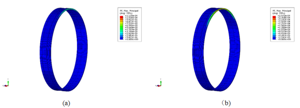
4.1.2. Failure Stage 2: The Cracking of P1’s Spigot End Inner Concrete Core
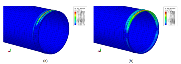
In step 2, the positive maximum principal plastic strains firstly appear on the top of spigot end inner concrete core at the relative rotation angle of 0.427˚ (calculated from Eq. (
1-3), which means the cracking of concrete, as shown in
Figure 8(a). After that, the cracking zone expands to the waist of spigot end inner concrete core with increase of the relative rotation angle, as shown in
Figure 8(b). The cracking of concrete can also lead to the abscission of inner concrete under the inner water pressure. Thus, 0.427˚ can be considered as the limit relative rotation angle of failure stage 2 in this situation. Using higher strength concrete can avoid this kind of failure.
Figure 8. Maximum principal plastic strains in concrete at the relative rotation angle of (a) 0.427˚; (b) 1.336˚.
The same results can also be obtained from the pipe rotation test.
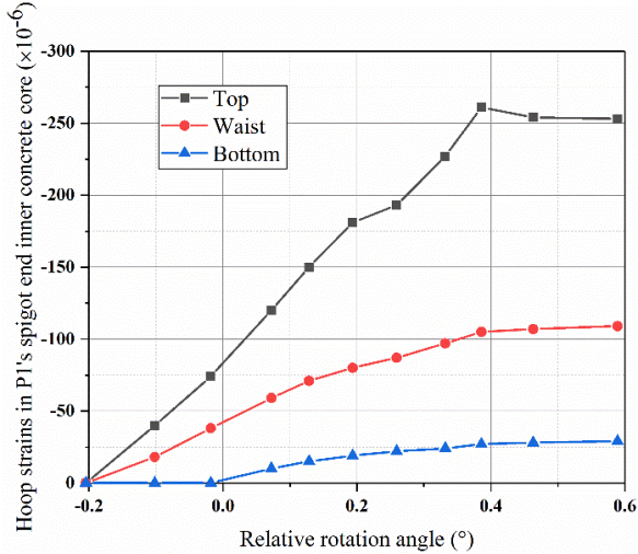
Figure 9 shows the relationship between hoop strains (tension stains are positive value and compressive strains are negative value) and relative rotation angles in spigot end inner concrete core. The hoop strain on the top of spigot end inner concrete core is almost linear up to the relative rotation angle of 0.386˚ and then decreases with the increase of the relative rotation angle. According to (Xu et al. 2008)
| [21] | Xu, S., Bu, D., and Zhang, X. (2008). "A study on double-K fracture parameters by using wedge-splitting test on compact tension specimens of various sizes." China Civil Engineering Journal, 41(2), 70-76(in Chinese). https://doi.org/10.3321/j.issn:1000-131X.2008.02.011 |
[21]
, cracks initiate in measuring points when the strains retract. Besides, in rotation test, cracks were also observed on the top of spigot end inner concrete core at the relative rotation angle of 0.386˚. 14. Furthermore, the limit relative rotation angle obtained from experimental results 0.386˚ is very close to that obtained from FEM results 0.427˚.
Figure 9. The relationship between hoop strains and relative rotation angles measured in rotation test.
4.1.3. Failure Stage 3: The Debonding of P1’s Spigot End Interface Layer
In step 2, when the relative rotation angle is up to 0.508˚, the interfacial debonding occurs in the top of spigot end interface layer and then expands towards the waist of interface layer. After that, the interfacial debonding appears below the waist of interface layer and then expands to the bottom of interface layer. The debonding in spigot end interface layer will result in the corrosion of steel cylinder if the exterior joint grout is destroyed. Therefore, 0.508˚ can be considered as the limit relative rotation angle of failure stage 3 in this situation. Measures such as improving the normal bonding force between concrete and the steel cylinder can effectively postpone this kind of failure.
4.1.4. Failure Stage 4: the Yielding of P1’s Steel Spigot Ring
In step 2, as the increase of the relative rotation angle, the contact stress between two pipes in joints increases gradually. Finally, the sealing groove in the top of the steel spigot ring yields at the relative rotation angle of 1.055˚ and then the plastic zone rapidly expands towards the waist of the rings, as shown in
Figure 10. At this angle, all other components in spigot end have been destroyed and the steel spigot ring is the only load bearing member. After that, a larger deformation occurs in the steel rings with the increase of the angle, which affects the water-tightness of joints and even results in the fracture in joints. Therefore, 1.055˚ can be considered as the limit relative rotation angle of failure stage 4 in this situation. Using higher yield strength steel can increase the value of limit relative rotation angle.
Figure 10. Maximum principal plastic strains in steel spigot ring at the relative rotation angle of (a) 0.427˚; (b) 1.336˚.
4.2. The Effects of Loading Modes on Joint Failure
The differences of loading modes exist in step 2, which means that only failure stage 2-4 may be affected by loading modes. The failure mode of loading mode 3 is similar to that in loading mode 1, while in loading mode 2, the relative rotation angle is negative and initial failure of each stage occurs in the bottom of joint components.
Table 3 shows the limit relative rotation angles of each stage in loading modes observed from FEM results and the comparison with test results. FEM results present that the settlements of double-end (bell end and spigot end) have a greater influence on the failure of joint structures than the settlements of single-end (bell end or spigot end) because the failure of major carrying components in joint (failure stage 2 and 4) first appears in loading mode 3. Moreover, the values of test results are lower than FEM results in failure stage 2, which is reasonable due to the defects in actual material. Although the relative error is up to 28% between test and FEM results in loading mode 2, the FEM results in loading mode 1 and 3 are in good agreement with test results (around 10%). This is acceptable, considering the randomness of initial cracks and measurement error. Therefore, FEM is effective to predict the failure stage 2.
Table 3. Limit relative rotation angles in different loading modes.
Loading mode | Limit relative rotation angles (absolute value) |
FEM results | Test results |
Failure stage 2 | Failure stage 3 | Failure stage 4 | Failure stage 2 |
1 | 0.427˚ | 0.508˚ | 1.055˚ | 0.386˚ |
2 | 0.513˚ | 0.428˚ | 1.492˚ | 0.371˚ |
3 | 0.398˚ | 0.525˚ | 0.952˚ | 0.351˚ |
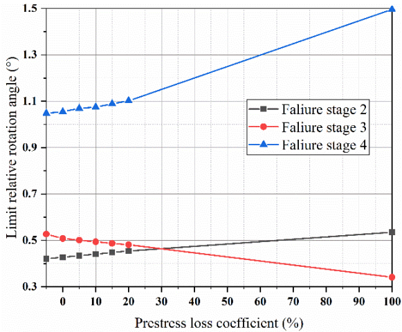
4.3. The Effects of Prestress Loss on Joint Failure
Generally, the prestress loss of bars occurs after applying prestress process, this means, it has no effect on the failure of stage 1. In this paper, by changing the value of prestress loss coefficient in Eq. (4) ranging from -5% to 100%, FEM simulates joint structure failure under different level of prestress. 100% of prestress loss coefficient means that there are broken bars in the joint. The relationship between limit relative rotation angles and prestress loss coefficients in different stages are shown in
Figure 11. It is shown that prestress loss has little influence on failure of all stages when the coefficient is small. Meanwhile, A linear relationship is observed between prestress loss coefficients and limit rotation angles in all failure stages. When the prestress loss coefficient reaches 100%, the limit rotation angle of failure stage 3 is up to the minimum value 0.341˚ while the limit rotation angles of failure stage 2 and 4 are up to the max maximum value 0.535˚ and 1.496˚, respectively. Consequently, lower level of prestress can improve carrying capacity of joints under the premise of no damage in the exterior joint grout.
Figure 11. The relationships between limit relative angles and prestress loss coefficients.
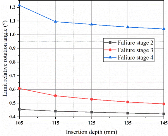
4.4. The Effects of Insertion Depth on Joint Failure
During the pipe installation process, the spigot end insertion depth usually can hardly match exactly with the standard value 135 mm. Similarly, failure stage 1 can’t be influenced by insertion depth. In this paper, the insertion depth was changed from 105 mm to 145 mm and the results are illustrated in
Figure 12. According to the figure, the limit relative rotation angles of all failure stages increase as the insertion depth decreases but the influence is little. Although shorter insertion depth can postpone the failure of all stages, excessively shorter insertion depth will result in the loss of water-tightness in joints. Thus, in practical project, all we need is to make sure that the actual insertion depth isn’t longer than the standard value 135 mm.
Figure 12. The relationships between limit relative angles and insertion depths.
4.5. The Effects of Pipe Types on Joint Failure
Different types of pipes are manufactured to meet different requirements of water transmission. In this paper, three other types of BCCP were modeled, whose parameters are shown in
Table 1. The FEM results of different pipe types are illustrated in
Table 4. The results show that besides failure stage 3, all other failure stages postpone with the increase of pipe inner diameter. However, in practical pipes, prestresses are increased in DN1800 and DN2000 by reducing the wrapping gap of bars, and therefore, in some failure stages, the limit value decreases slightly. Overall, carrying capacity of joints in larger inner diameter pipes are higher than small inner diameter pipes.
Table 4. Limit states of different pipe types.
Pipe type | Limit prestress level | Limit relative rotation angles |
Stage 1 | Stage 2 | Stage 3 | Stage 4 |
DN1400 | 49% | 0.427˚ | 0.508˚ | 1.055˚ |
DN1600 | 52% | 0.508˚ | 0.479˚ | 1.235˚ |
DN1800 | 61% | 0.588˚ | 0.454˚ | 1.316˚ |
DN2000 | 75% | 0.628˚ | 0.434˚ | 1.489˚ |
DN1800 (actual) | 56% | 0.575˚ | 0.521˚ | 1.281˚ |
DN2000 (actual) | 66% | 0.609˚ | 0.488˚ | 1.444˚ |
4.6. The Effects of Inner Water Pressure on Joint Failure
It is assumed that BCCP works under maximum internal water pressure 2 MPa and an extra analysis step was created before step 2 to apply pressure on the inner wall of pipes. According to FEM results, the failure mode is similar to the case without inner water pressure and the limit relative rotation angles of failure stage 2, 3 and 4 are 0.247˚, 0.868˚ and 1.049˚, respectively. Comparison between the limit relative rotation angles of models with and without inner water pressure, shows that under the influence of inner water pressure, failure stage 2 appears much earlier while failure stage 3 postpones, but failure stage 4 is almost unchanged. In a word, the exist of inner water pressure will accelerate the failure of spigot end inner concrete core at early stage, which should be paid more attention in the pipe operation process.
5. Conclusions and Recommendations
In this paper, a local refinement three-dimensional BCCP numerical model was established to investigate the mechanical properties of joints under different relative rotation angles, implemented in ABAQUS. CDPM was used in this model to simulate nonlinear response of concrete under complex loading and cohesive elements were applied to simulate the debonding between steel cylinder and concrete. The failure of joint structures is determined by three indicators: the debonding of the interface layer, the cracking of concrete, and yielding of the steel ring. Meanwhile, five factors that affect the failure of joint structures are considered, including prestress loss, insertion depth, loading modes, pipe types and inner water pressure. In addition, rotation tests of pipes were carried out to obtain mechanical response of joint structures under different relative rotation angles and compare with results obtained from the numerical method.
The results show that, generally, the whole failure process of joint structures can be divided into four stages, that is, the debonding of bell end interface layer, the cracking of spigot end inner concrete core, the debonding of spigot end interface layer and the yielding of steel spigot ring, arranged in the order of failure occurrence. All the limit values corresponding to different failure stages can be achieved from FEM results while only failure stage 2 can be observed from the experimental results, but numerical results show good agreement with experimental results in the limit relative rotation angles of failure stage 2, which proves that FEM is effective to predict the failure of joint structures. Additionally, lower level of prestress, shorter insertion depth, lager inner diameter pipes can improve carrying capacity of joint structures. But the exist of inner water pressure will accelerate the failure of spigot end inner concrete core at early stage.
In conclusion, the failure of BCCP joint structures is close related to the relative rotation angles between pipes and many factors need to be considered to determine the limit values of different failure stages using experimental and numerical methods. These limit values can provide references for evaluating the failure state of BCCP joints in engineering.