Review Article | | Peer-Reviewed

Defect Assessment with DAC and DAM Methods; Measurement Accuracy Problems

Received: 26 May 2025     Accepted: 7 July 2025     Published: 9 October 2025
Views:       Downloads:
Abstract

Conventional pulse-echo ultrasonic inspection uses the ratio of the signal from a crack-like defect to the signal from a reference reflector as one factor which determines whether the flaw merits reporting, further sizing, and, possibly, removal. As these defects are smooth, on the scale of an ultrasonic wavelength, and generally flat, and also large relative to the wavelength, they can be successfully modelled using the geometrical theory of diffraction (GTD). GTD is a rapid method for evaluating the ultrasonic signal from a defect. The signal from the reference reflector is easy to calculate if the reflector is a side-drilled hole whose axis is normal to the ultrasonic beam axis and provided it is in the far field of the transducer. If the reference reflector is a flat-bottomed hole then prediction of the signal for non-normal angles of incidence is more difficult since the signal arises from the curved edge at the intersection of the flat bottom of the hole and its cylindrical side face.

Published in International Journal of Mineral Processing and Extractive Metallurgy (Volume 10, Issue 4)
DOI 10.11648/j.ijmpem.20251004.11
Page(s) 89-95
Creative Commons

This is an Open Access article, distributed under the terms of the Creative Commons Attribution 4.0 International License (http://creativecommons.org/licenses/by/4.0/), which permits unrestricted use, distribution and reproduction in any medium or format, provided the original work is properly cited.

Copyright

Copyright © The Author(s), 2025. Published by Science Publishing Group

Keywords

Geometrical Theory of Diffraction, Kirchhoff's Approximation, Wave Transformations, Diffraction Coefficient

1. Introduction
In the field of ultrasonic testing there are two key questions: Which defects can be found and – in the case indications are found – do they restrict the use of the part?
Regarding both questions, the prerequisite is a method for defect sizing.
Over the last decades sizing methods were established like DGS (Distance Gain Size) or DAC (Distance Amplitude Correction) for defects smaller than the beam profile. Those methods utilize the echo amplitude and provide results which are proportional to the defect area. However, those approximations are only accurate for defects larger than one wavelength even that experience shows it can be applied for slightly smaller defects.
With the progress of material technology and ultrasonic inspection the need to detect and size smaller defects is growing. Therefore, both for flat bottom holes and disc shaped reflectors the usability for small defects needs to be checked.
In this publication, it is investigated how to correctly size small defects below one wavelength. Utilizing a grid-based simulation method the echo signals of cylinder and disc shaped reflectors of various sizes are calculated.
2. The Surface-amplitude Relationship
The surface-amplitude relationship is a consequence of using Kirchhoff's approximation (also called physical optics) when solving the equation governing the behavior of ultrasound with a flat-bottomed hole as a solution.
This approximation assumes that the motion of the surface of the flat-bottomed hole, when it reflects an ultrasonic pulse, is identical to the motion that would occur if the pulse were reflected by an infinite flat surface.
The next hypothesis applicable to the surface-amplitude relationship would be that a finite-diameter ultrasonic beam can be approximated as a plane wave with infinite surface. Following this hypothesis, it can be seen that the motion of the surface of the flat-bottomed hole is independent of the size of the hole.
The reciprocal of Auld 's formula states that the voltage (respectively the amplitude of the signal on the ultrasonic gauge screen) caused by a defect is equal to the integral on the defect surface of the product between the traction generated by the incident pulse in the absence of the defect multiplied by the total surface movement. In the case of flat-bottomed holes, using Kirchhoff's approximation for an incident plane wave, it is easy to see that Auld's formula predicts a voltage directly proportional to the surface of the flat-bottomed hole, namely the so-called surface-amplitude relationship (Figure 1).
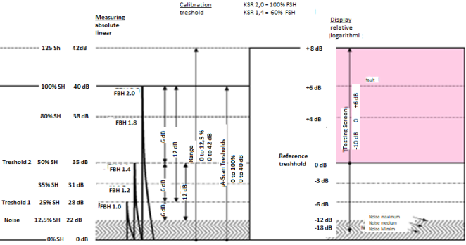
Figure 1. Graphical representation of the surface/amplitude relationship .
The relationship between the response echo of a flat-bottomed hole and its diameter has been formulated since the beginning of the development of the non-destructive ultrasonic control method.
Krautkramer refers to this flat-bottomed hole as a disc-shaped reflector and has developed the well-known method of evaluating a response in relation to curves corresponding to different diameters of disc reflectors, curves built for each type of transducer and called AVG.
The mathematical relationship between the amplitude of the echo, transducer and the diameter of the flat-bottomed hole can be expressed in the equation:
VfV0=SAλ21T2e-2(1)
where:
V f = maximum amplitude of the echo at the target;
V0 = maximum possible signal if all initial energy is returned to the receiver;
T = distance to the target on the beam axis;
A = surface of the defect;
S = surface of the transducer;
λ = wavelength;
δ = specific attenuation coefficient.
According to Krautkramer's observations, we can say that the amplitude of the signal from a flat-bottomed hole is proportional to its surface. Therefore, having a signal of a certain amplitude on the cathode screen given by a flat-bottomed hole (in the linear amplification region of the instrument display), the response from a flat-bottomed hole with an area equal to half its surface will produces a signal with an amplitude equal to half the amplitude of the initial signal and a hole with a double surface will produce a signal with an amplitude twice the amplitude of the initial signal.
2.1. Deviations from the Surface-amplitude Relationship
A physical phenomenon that both Kirchhoff's approximation and Krautkramer's theories do not they took into account is the phenomenon of wave diffraction produced at the edges of flat-bottomed holes.
According to Geometrical Theory of Diffraction (GTD), an incident acoustic field on the edge obtained by the intersection of two non-coplanar surfaces forms diffracted waves that propagate from the point of intersection with the edge in the form of a cone (Figure 2).
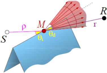
Figure 2. Diffracted wave by a 3D edge in the situation of oblique incidence .
In the case of oblique incidence, an incident wave gives rise to a cone of diffracted waves. The angle of the cone ϴd is equal to the angle between the incident wave and the edge, ϴi.
We aim to analyze the situation when a flat compression wave with normal incidence reaches the flat surface of a flat-bottomed hole and suffers the phenomenon of diffraction from its circular edge, a phenomenon analyzed through the GTD prism (Figure 3).
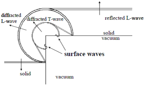
Figure 3. Diffraction phenomena and wave transformations on the flat surface of the flat-bottomed hole .
Figure 3. show the different diffraction phenomena that occur for a plane compression wave with an incidence perpendicular to the bottom of the hole. It can be seen that, in addition to the reflected compression waves, diffracted compression waves and transverse waves are generated together with surface waves propagating along the cylindrical surface and the flat surface of the flat-bottomed hole.
Of interest are the surface waves that propagate on the flat surface of the flat-bottomed hole.
After meeting the opposite corner of the flat surface, the surface waves undergo a second diffraction during which a small amplitude compression wave is emitted from the edge of the flat-bottomed hole.
Part of this diffracted wave a second time goes to the transducer, a short distance from the main compression wave reflected by the flat-bottomed hole surface, as shown in Figure 4 and is received as a small amplitude signal at the end of the main signal, as shown in Figure 5.
The time interval between the two waves is given by the ratio between the diameter of the flat-bottomed hole and the speed of the surface wave.
If the time delay between these two signals is sufficiently small, an interaction could take place that would enhance or reduce the total signal amplitude through a constructive or destructive interference. Such an interaction might be the cause of the deviation from the area-amplitude relation seen in experiments when looking at small reflectors. (Figure 6)
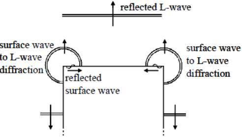
Figure 4. Longitudinal wave obtained by diffraction from the surface wave and succeeding the reflected longitudinal wave .
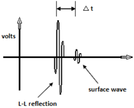
Figure 5. Two signals that reach the transducer staggered in time (Δt decreases with decreasing hole diameters) .
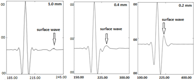
Figure 6. Dependence of time differences on the diameter of the flat-bottomed hole .
2.2. Differences in Response Between Different Types of Ultrasonic Beams
Experimentally, it was observed that two flat-bottomed holes of different sizes but at the same depth in a reference block return, under the same examination conditions, signals in a ratio that does not respect the fundamental surface / amplitude relationship but at the same time is depending on the type of ultrasonic beam focusing.
Thus, the differences between the theoretical ratios (calculated by Kirchhoff's approximation) and the real ones are larger for focused immersion transducers than for non-focused ones, at the same diameter of the piezoelectric crystal, frequency and water path.
The explanation of this phenomenon and its quantitative evaluation can be done by applying the theory of geometric diffraction - GTD.
For a monochrome harmonic wave, the sound pressure of the diffracted field by one edge (Figure 7) can be expressed as a function of the incident ξ incident field (M) as follows:
ξdiffracted(R)=ξincident(M)DA(r,ρ)e-ikr(2)
where:
R = receiver location;
M = the point on the edge where the diffraction is made;
K = 2π / λ = wave number;
λ = wavelength;
A = √ (ρ r / (ρ + r)) = attenuation as a function of distance;
D = diffraction coefficient calculated according to GTD.
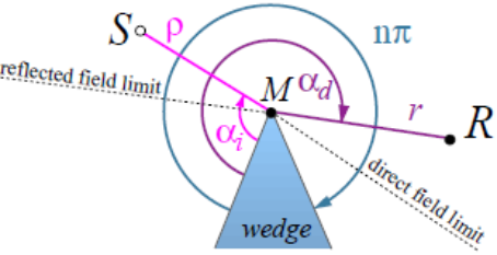
Figure 7. Coordination system for defining the diffraction coefficient .
The diffraction coefficient D is a complex number that takes into account the amplitude and phase change due to diffraction and depends on the angle of incidence αi, the angle of refraction αd and the angle of the half-planes forming the edge, nπ.
In order to perform interactive evaluations, an independent frequency relationship can be implemented, which uses the scalar values of the incident and diffracted wave amplitude .
Adiffracted=AincidentDA(ρ,r)(3)
where:
A = scalar value of amplitude;
D = diffraction coefficient.
The diffraction coefficient D calculated according to GTD has the following formula :
D=e4n(2πk)1/2sinπnsinβcosπn-cosαd-αin-1±cosπn-cosαd+αi+πn-1(4)
where:
β = angle between incident wave and edge;
αi = angle of incidence;
αd = diffraction angle;
nπ = the angle between the half-planes that form the edge.
We propose to calculate the numerical values of the diffraction coefficient for a flat wave incident on the surface of the flat-bottomed hole as a function of the angle of incidence αi, the other parameters respectively β and the diffraction angle αd remaining constant.
Calculate the numerical value of the factor in square brackets in equation (4), giving successive values for αi in the range of 135° ÷ 180°, with the value of the increment of one degree. Python calculator version 3.7 was used with two open-source modules (Pandas and Math) that include an extensive range of predefined math. functions.
The following terms have constant values as follows:
β = π/2;
αd = diffraction angle = 3/2π;
n = 3/2.
The results of the partial calculations of the diffraction coefficient D are presented below.
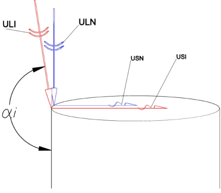
Figure 8. The phenomenon of diffraction on the edges of the flat-bottomed hole of the longitudinal waves and the appearance of the surface waves.
An increase in the values of the modulus of the diffraction coefficient D is observed as the angle of deviation increases from normal to the surface of the flat-bottomed hole, respectively the difference between the angle of incidence of the ULI longitudinal wave and the angle of incidence of the normal longitudinal wave at the hole surface, ULN.
As a result, the amplitude of the USI surface wave (Figure 8.) generated by the diffraction of the ULI longitudinal wave will be higher than the USN surface wave generated by the ULN normal incidence wave, according to equation (3). The USI diffracted wave will cross the flat surface of the hole and a second diffraction will occur when it reaches the edge of the surface at the diametrical point opposite to the starting point (Figure 4).
The amplitude of the longitudinal wave resulting from this second diffraction of the USI surface wave will be greater than that of the longitudinal wave obtained from the second diffraction of the USN surface wave.
As shown in Figure 5, the longitudinal waves obtained by these secondary diffractions they occur at short intervals following the reflected longitudinal wave and may interfere with it, altering its amplitude.
This could be the case in practice with ultrasonic immersion examination with a focused transducer, with a focusing angle of up to 30° (depending on the focal length in water and material) compared to examination with an unfocused immersion transducer or a direct contact transducer.
3. Results
The experimental results obtained by scanning a flat reference block provided with several pairs of holes positioned at different depths (Figure 9) confirm this explanation.
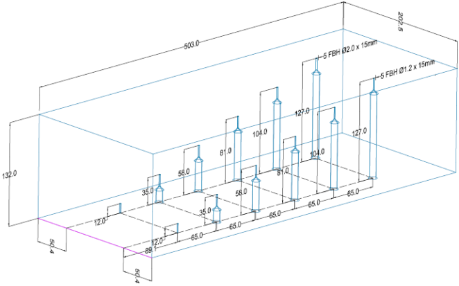
Figure 9. Forged plate examination reference block.
The main problem in determining the significance of the interaction of surface waves is the quantitative determination of the amplitude of diffracted signals.
According to GTD, the ratio of the amplitudes of the diffracted waves, measured at the same point in the diffraction field, is proportional to the ratio of the diffraction coefficients D corresponding to each wave.
In order to quantitatively evaluate the deviations from the surface/amplitude relationship, the ratio of the diffraction coefficients can be expressed in dB. For relatively close angles, which corresponds to the real differences between a focused and a non-focused transducer, it is found that these differences are in the range of 2-3 dB, values corresponding to the errors encountered in practice (Table 1).
Calculation of diffraction coefficients D
ecuatie - grad=134 ->>> angle -1.32
ecuatie - grad=135 ->>> unghi -1.27
ecuatie - grad=136 ->>> unghi -1.22
ecuatie - grad=137 ->>> unghi -1.17
ecuatie - grad=138 ->>> unghi -1.13
ecuatie - grad=139 ->>> unghi -1.08
ecuatie - grad=140 ->>> unghi -1.04
ecuatie - grad=141 ->>> unghi -1.00
ecuatie - grad=142 ->>> unghi -0.96
ecuatie - grad=143 ->>> unghi -0.93
ecuatie - grad=144 ->>> unghi -0.89
ecuatie - grad=145 ->>> unghi -0.86
ecuatie - grad=146 ->>> unghi -0.82
ecuatie - grad=147 ->>> unghi -0.79
ecuatie - grad=148 ->>> unghi -0.76
ecuatie - grad=149 ->>> unghi -0.72
ecuatie - grad=150 ->>> unghi -0.69
ecuatie - grad=151 ->>> unghi -0.67
ecuatie - grad=152 ->>> unghi -0.64
ecuatie - grad=153 ->>> unghi -0.61
ecuatie - grad=154 ->>> unghi -0.58
ecuatie - grad=155 ->>> unghi -0.55
ecuatie - grad=156 ->>> unghi -0.53
ecuatie - grad=157 ->>> unghi -0.50
ecuatie - grad=158 ->>> unghi -0.48
ecuatie - grad=159 ->>> unghi -0.45
ecuatie - grad=160 ->>> unghi -0.43
ecuatie - grad=161 ->>> unghi -0.40
ecuatie - grad=162 ->>> unghi -0.38
ecuatie - grad=163 ->>> unghi -0.36
ecuatie - grad=164 ->>> unghi -0.33
ecuatie - grad=165 ->>> unghi -0.31
ecuatie - grad=166 ->>> unghi -0.29
ecuatie - grad=167 ->>> unghi -0.27
ecuatie - grad=168 ->>> unghi -0.25
ecuatie - grad=169 ->>> unghi -0.23
ecuatie - grad=170 ->>> unghi -0.20
ecuatie - grad=171 ->>> unghi -0.18
ecuatie - grad=172 ->>> unghi -0.16
ecuatie - grad=173 ->>> unghi -0.14
ecuatie - grad=174 ->>> unghi -0.12
ecuatie - grad=175 ->>> unghi -0.10
ecuatie - grad=176 ->>> unghi -0.08
ecuatie - grad=177 ->>> unghi -0.06
ecuatie - grad=178 ->>> unghi -0.04
ecuatie - grad=179 ->>> unghi -0.02
Table 1. Values of amplitude response differences for focused and unfocused transducers.

Reflector

Unfocused transducer Φ 19 mm, 4 MHz

Focused transducer Φ 19 mm, F=200 mm, 5 MHz

FBH 1.2

FBH 2,0

Δ1 [dB]

FBH 1.2

FBH 2,0

Δ2 [dB]

Δ2 - Δ1 [dB]

G2

49.5

44.3

5.2

36.8

29.5

7.3

2.1

G3

50.5

42.6

7.9

43.3

33.5

9.8

1.9

G4

51,1

39.1

12.0

46.7

32.4

14.3

2.3

G5

48.0

40.7

7.3

45.0

35.5

9.5

2.2

Note: Holes in the immediate vicinity of the upper and lower surfaces were not included in the experiment because they are located in critical areas of the ultrasonic field.
4. Conclusions
The phenomenon of deviation from the surface-amplitude relationship as a consequence of using Kirchhoff's approximation when solving the equation governing the behavior of ultrasound for flat-bottomed holes with a diameter smaller than the wavelength has been known and studied for a long time. The present material aims to analyze and quantify to a certain extent the differences in behavior between focused and non-focused ultrasonic immersion transducers, placed in the situation of analyzing such artificial reflectors. For this, the general diffraction theory (GTD) was used with the particularization of the diffraction coefficient (D). Practical experiments confirmed the theoretical results.
Abbreviations

GTD

Geometrical Theory of Diffraction

ULI

Longitudinal Incident Angled Wave

ULN

Longitudinal Incident Normal Wave

USI

Diffracted Wave Generated by ULI

USN

Diffracted Wave Generated by ULN

Acknowledgments
This work was supported by S. C. ZIROM-S. A – Giurgiu - ROMANIA and was performed by the NDT Consulting Company - DIAC SERVICII srl and AROEND -Romania.
Conflicts of Interest
The authors declare no conflicts of interest.
References
[1] V. Dorval, S. Chatillon, B. Lu, M. Darmon, S. Mahaut-A general Kirchhoff approximation for echo simulation in ultrasonic NDT- CEA, LIST, F-91191 Gif-sur-Yvette, France, 2019
[2] Alexander Seeber, Johannes Vrana, Hubert Mooshofer and Matthias Goldammer -Correct sizing of reflectors smaller than one wavelength - Siemens AG, Germany, Ludwig-Maximilians- Universität Munich, Germany-2018.
[3] Darmon, M., Dorval, V. & Kamta Djakou, A., A system model for ultrasonic NDT based on the Physical Theory of Diffraction (PTD). Ultrasonics, 64, pp. 115–127, 2016.
[4] BA Auld - “Acoustic felds and waves in solids” vol. ii, 1990.
[5] J Krautkrämer: “Fehlergrößenermittlung mit Ultraschall”, Archiv für Eisenhüttenwesen 30, pp. 693-703, 1959.
[6] Geometrical Theory of Diffraction for Modeling Acoustics in Virtual Environments-online ID: papers 187-2000.
[7] Margetan, F. J., Umbach, J., Roberts - Inspection development for titanium forgings - Iowa State University -2006.
[8] J. Ernest Gotta (Author), Daniel Kirchheimer (Author), George Rimakis (Author)-SAT Math Orange Book Volume II: Every SAT Math Topic, Patiently Explained (1600. io SAT Math Orange Book 2-volume set).
Cite This Article
  • APA Style

    Theodor, T., Mircea, T., Vasile, C. C. (2025). Defect Assessment with DAC and DAM Methods; Measurement Accuracy Problems. International Journal of Mineral Processing and Extractive Metallurgy, 10(4), 89-95. https://doi.org/10.11648/j.ijmpem.20251004.11

    Copy | Download

    ACS Style

    Theodor, T.; Mircea, T.; Vasile, C. C. Defect Assessment with DAC and DAM Methods; Measurement Accuracy Problems. Int. J. Miner. Process. Extr. Metall. 2025, 10(4), 89-95. doi: 10.11648/j.ijmpem.20251004.11

    Copy | Download

    AMA Style

    Theodor T, Mircea T, Vasile CC. Defect Assessment with DAC and DAM Methods; Measurement Accuracy Problems. Int J Miner Process Extr Metall. 2025;10(4):89-95. doi: 10.11648/j.ijmpem.20251004.11

    Copy | Download

  • @article{10.11648/j.ijmpem.20251004.11,
      author = {Tranca Theodor and Tranca Mircea and Cucuzel Cătălin Vasile},
      title = {Defect Assessment with DAC and DAM Methods; Measurement Accuracy Problems},
      journal = {International Journal of Mineral Processing and Extractive Metallurgy},
      volume = {10},
      number = {4},
      pages = {89-95},
      doi = {10.11648/j.ijmpem.20251004.11},
      url = {https://doi.org/10.11648/j.ijmpem.20251004.11},
      eprint = {https://article.sciencepublishinggroup.com/pdf/10.11648.j.ijmpem.20251004.11},
      abstract = {Conventional pulse-echo ultrasonic inspection uses the ratio of the signal from a crack-like defect to the signal from a reference reflector as one factor which determines whether the flaw merits reporting, further sizing, and, possibly, removal. As these defects are smooth, on the scale of an ultrasonic wavelength, and generally flat, and also large relative to the wavelength, they can be successfully modelled using the geometrical theory of diffraction (GTD). GTD is a rapid method for evaluating the ultrasonic signal from a defect. The signal from the reference reflector is easy to calculate if the reflector is a side-drilled hole whose axis is normal to the ultrasonic beam axis and provided it is in the far field of the transducer. If the reference reflector is a flat-bottomed hole then prediction of the signal for non-normal angles of incidence is more difficult since the signal arises from the curved edge at the intersection of the flat bottom of the hole and its cylindrical side face.},
     year = {2025}
    }
    

    Copy | Download

  • TY  - JOUR
    T1  - Defect Assessment with DAC and DAM Methods; Measurement Accuracy Problems
    AU  - Tranca Theodor
    AU  - Tranca Mircea
    AU  - Cucuzel Cătălin Vasile
    Y1  - 2025/10/09
    PY  - 2025
    N1  - https://doi.org/10.11648/j.ijmpem.20251004.11
    DO  - 10.11648/j.ijmpem.20251004.11
    T2  - International Journal of Mineral Processing and Extractive Metallurgy
    JF  - International Journal of Mineral Processing and Extractive Metallurgy
    JO  - International Journal of Mineral Processing and Extractive Metallurgy
    SP  - 89
    EP  - 95
    PB  - Science Publishing Group
    SN  - 2575-1859
    UR  - https://doi.org/10.11648/j.ijmpem.20251004.11
    AB  - Conventional pulse-echo ultrasonic inspection uses the ratio of the signal from a crack-like defect to the signal from a reference reflector as one factor which determines whether the flaw merits reporting, further sizing, and, possibly, removal. As these defects are smooth, on the scale of an ultrasonic wavelength, and generally flat, and also large relative to the wavelength, they can be successfully modelled using the geometrical theory of diffraction (GTD). GTD is a rapid method for evaluating the ultrasonic signal from a defect. The signal from the reference reflector is easy to calculate if the reflector is a side-drilled hole whose axis is normal to the ultrasonic beam axis and provided it is in the far field of the transducer. If the reference reflector is a flat-bottomed hole then prediction of the signal for non-normal angles of incidence is more difficult since the signal arises from the curved edge at the intersection of the flat bottom of the hole and its cylindrical side face.
    VL  - 10
    IS  - 4
    ER  - 

    Copy | Download

Author Information
  • AROEND, Bucuresti, Romania

  • DIAC SERVICII srl, Bucuresti, Romania

  • International Gear WATTEEUW Romania srl, Iasi, Romania