Abstract
Currently, the thickness of the elements of pressure vessels is often determined by calculation according to the formulas in ASME Code Section VIII or numerical simulation using mechanical calculation software. Calculations according to the ASME Code often give results with much excess durability, while conventional numerical simulation calculations will take a lot of time due to manual detection and depend heavily on the experience of the designer. Both of the above methods are very difficult to determine the optimal value of design variables (thickness of the structure) to ensure the most workability and material savings. This paper presents an automatic calculation method to determine the optimal thickness of the elements of a pressure vessel through a new self-developed simulation algorithm, in which all the stages of a conventional numerical simulation problem have been wrapped into an automatic loop “– modeling – solve – evaluate results – remodeling –”. A computer program written in the APDL language of ANSYS software, based on this new algorithm, has automatically determined the optimal value of the thicknesses of the pressure vessel regardless of its initially selected preliminary values. That is, starting from any preliminary value of the design variables, the computer program will automatically calculate to determine the optimal value of the design variables that ensure the structure satisfies the working conditions and has the smallest mass or volume. Applying this method, the volume of the considered heat-exchange pressure vessel was reduced from 0.50658 m3 to 0.41970 m3, which means that 0.08688 m3 or 677.664 kg of steel was saved.
Keywords
Design Optimization, Optimal Design, Numerical Simulation, Pressure Vessel, Welded Structure, Design Variable, Computation Program, APDL Language
1. Introduction
Heat-exchange pressure vessel is a special type of pressure vessel, it is used to exchange the heat between one or more heat carriers, which can be separated by tubes or plates to prevent mixing or direct contact between heat carriers. Beam tube heat exchangers are widely used in thermal power, petrochemical, air conditioning, chemical, food industry, and shipbuilding industries, etc. The heat exchanger is used to heat or cool the solvent, depending on each specific purpose. In the general industry, heat exchangers often use steam, hot oil, hot air, or a high-temperature medium to heat the water or another medium to the required temperature.
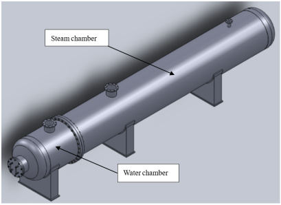
The beam tube heat exchanger operates on the principle of indirect heat exchange between two moving fluids or steam inside and outside the heat exchanger tube. To enhance the efficiency of heat exchange, the flow direction of the fluid inside and outside the tube is created in a perpendicular or diagonal direction. The heat exchanger vessel is usually made up of two chambers (
Figure 1) to supply liquid and/or steam inside and outside of the heat exchanger tube.
The shell of the heat exchanger vessel is a welded structure, they are made of metal plates shaped by rolling and flanging processes, so the optimal computation of the thickness of the structure is very necessary and has great significance not only in terms of production cost but also greatly facilitates in the fabrication process.
Figure 1. Product overview.
Currently, the calculation of the thickness of the pressure vessel parts is often based on the empirical formulas in the ASME Code Section VIII
| [1] | Mayank Nirbhay, Prashant Tripathi, Vivek Kumar Gupta, “Implementation of ASME Codes to Design a Pressure Vessel and Toexplore the Influence of Various Design Parameters”, International Journal of Engineering Research & Technology (IJERT), 1014, 3(1), pp. 2497- 2504. |
| [2] | Thakkar, B. S., Thakkar, S. A., “Design of Pressure Vessel Using ASME Code, Section VIII, Division 1”, International Journal of Advanced Engineering Research and Studies, 2012, 1(3), pp. 228-234, https://doi.org/10.21467/proceedings.4.33 |
| [3] | Jegatheesan, J. and Zulkifli Zakaria, “Stress analysis on pressure vessel”, Environment & Ecosystem science, 2012, 2(2), pp. 53-57, https://doi.org/10.26480/ees.02.2018.53.57 |
| [4] | Parkhe, S., Annamalai, K., “Design and Analysis of Pressure Vessel Subjected to Pressure-temperature Variation”, International Journal of Engineering, IJE Transactions A: Basics, 2018, 31(1), pp. 58-64, https://doi.org/10.5829/ije.2018.31.01a.09 |
| [5] | Niranjana, S. J., Smit Vishal Patel, Ankur Kumar Dubey, “Design and Analysis of Vertical Pressure Vessel using ASME Code and FEA Technique”, IOP Conf. Series: Materials Science and Engineering, 2018, 376, 012135. https://doi.org/10.1088/1757-899X/376/1/012135 |
| [9] | Arun Kumar, M. H., Manjunath, S., Amith Kumar, S. N., “Design of pressure vessel using ASME codes and a comparative Analysis using FEA”, International Research Journal of Engineering and Technology (IRJET), 2017, 4(11), pp. 617- 625. |
[1-5, 9]
. This work always creates products with high working reliability, but the products often exceed durability, leading to wastage of materials, increasing manufacturing costs, and making it difficult to fabricate. In particular, the required minimum thickness of structural parts for the specific load-bearing conditions is not known exactly.
Nowadays, with the great help of high-speed computers and powerful numerical simulation software, design computations have become very fast. The application of numerical simulation analysis will support engineers and researchers in understanding the nature of the structure and the behavior of the material under a specific load, thereby giving the optimal design plan to save materials and costs, convenient for fabrication. Quite a lot of authors have used numerical simulation in calculating pressure vessels
| [6] | Rafiq Rustam, Ahmad Faiz Ahmad Nazri, Md Rizal Md Tasliman, and Jamaluddin Mahmud, “Finite Element Simulation and Analysis for the Design of a Pressure Vessel with Expansion Joint”, International Journal of Materials, Mechanics and Manufacturing, 2018, 6(4), pp. 268- 272, https://doi.org/10.18178/ijmmm.2018.6.4.389 |
| [7] | Farid Ahmed, Md Minaruzzaman Sumon, Muhtasim Fuad, Ravi Gugulothu, AS Mollah, “Numerical Simulation of Heat exchanger for analyzing the performance of parallel and counter flow”, WSEAS Transactions on Heat and Mass Transfer, Volume 16, 2021, pp. 145-152, https://doi.org/10.37394/232012.2021.16.17 |
| [8] | Vishal V. Saidpatil, Arun S. Thakare, “Design & Weight Optimization of Pressure Vessel Due to Thickness Using Finite Element Analysis”, International Journal of Emerging Engineering Research and Technology, 2014, 2(3), pp. 1-8. |
| [9] | Arun Kumar, M. H., Manjunath, S., Amith Kumar, S. N., “Design of pressure vessel using ASME codes and a comparative Analysis using FEA”, International Research Journal of Engineering and Technology (IRJET), 2017, 4(11), pp. 617- 625. |
| [10] | Jie Dou, Fude Wang, “Simulation study on optimization design of small gas water heat exchangers”, Journal of Physics: Conference Series 2835 (2024) 012070, Volume 2835, pp. 1-6, https://doi.org/10.1088/1742-6596/2835/1/012070 |
| [11] | Zengliang Chen, Ye Luo, Zhihui Wang, Yulin Liu, Limei Gai, Qichao Wang and Bingyuan Hong, “Optimization Design and Performance Study of a Heat Exchanger for an Oil and Gas Recovery System in an Oil Depot”, Energies 2024, 17, 2631. https://doi.org/10.3390/en17112631 |
| [12] | Juanjuan Wang, Jiangping Nan and Yanan Wang, “CFD-Based Optimization of a Shell-and-Tube Heat E xchanger”, Fluid Dynamics & Materials Processing, FDMP, 2023, vol. 19, no. 11, pp. 2761-2775, https://doi.org/10.32604/fdmp.2023.021175 |
| [13] | Chongyang Wang, Weiting Jiang, Weiguo Pan, Tingni He, “Structure Optimization and Numerical Simulation of Micro Gas Turbine Regenerator”, Journal of Physics: Conference Series, Volume 2296 (2022) 012005, pp. 1-6, https://doi.org/10.1088/1742-6596/2296/1/012005 |
[6-13]
, but mainly stopped at evaluating the durability of pressure vessels without giving the optimal design plan. Currently, there are some authors
| [8] | Vishal V. Saidpatil, Arun S. Thakare, “Design & Weight Optimization of Pressure Vessel Due to Thickness Using Finite Element Analysis”, International Journal of Emerging Engineering Research and Technology, 2014, 2(3), pp. 1-8. |
| [13] | Chongyang Wang, Weiting Jiang, Weiguo Pan, Tingni He, “Structure Optimization and Numerical Simulation of Micro Gas Turbine Regenerator”, Journal of Physics: Conference Series, Volume 2296 (2022) 012005, pp. 1-6, https://doi.org/10.1088/1742-6596/2296/1/012005 |
[8, 13]
who calculate the optimal structure of the pressure vessel, but only stopped at the simple calculation about the structure and design variables without programming of automatic computation to find the optimal design as mentioned in this article.
2. Theoretical Basis
2.1. Digitization of Integral Equations of the Structural Problem by Finite Element Method (FEM)
The principle of virtual work states that a virtual (very small) change of the internal strain energy must be offset by an identical change in external work due to the applied loads:
Where U is the strain energy (internal work) due to the possible cause () and V is generated by external forces (), is the differential symbol (virtual operator).
The first component of the virtual strain energy is determined bythe following formula
| [14] | ANSYS Inc., Theory reference for the ANSYS and Workbench Product, 2018, Version 19.1. |
[14]
:
Here: is the overall strain vector, is the stress vector and is the volume of the survey element. Call the [D] is the stiffness matrix, then:
(3)
With {
el} is the elastic strain vector and {
th} is the thermal strain vector. Combining the Eq. (
3) and (
2) we obtain:
(4)
If we call is the strain - displacement matrix on the basis of the element shape functions and is the nodal displacement vector, we have:
Substitute the Eq. (
5) into Eq. (
4) we obtain:
(6)
The second component of the virtual strain energy is determined when a surface moves against a distributed resistance, as in a foundation stiffness, it is described by the following formula
| [14] | ANSYS Inc., Theory reference for the ANSYS and Workbench Product, 2018, Version 19.1. |
[14]
:
Here: is the motion normal to the surface, is the vector of stresses on the surface, is area of the distributed resistance. The point-wise normal displacement is related to the nodal displacements by:
Where is matrix of shape functions for normal motions at the surface. The stress, {σ}, is
With k is the foundation stiffness in units of force per length per unit area.
Combining the formulas (
7), (
8), (
9) and assuming that k is constant over the area, we obtain:
(10)
Next, the external virtual work will be considered, in that the inertial effects will be studied first. The first component of the external forces is considered based on inertial effects as follow
| [14] | ANSYS Inc., Theory reference for the ANSYS and Workbench Product, 2018, Version 19.1. |
[14]
:
Here is vector of displacements of a general point, is acceleration (D'Alembert) force vector.
According to the second law of Newton, we have:
Where is density of the structure material, t is time variable.
The displacements within the element are related to the nodal displacements by:
where [N] = matrix of shape functions. Combining formulas (
11), (
12), (
13) and assuming that ρ is constant over the volume, we obtain:
(14)
Vectors of pressure loads are determined by the following formula
| [14] | ANSYS Inc., Theory reference for the ANSYS and Workbench Product, 2018, Version 19.1. |
[14]
:
With
is the applied pressure vector,
is the surface on which the pressure load put on. Combining the formulas (14) and (
15), we obtain:
Nodal force acting on the elements
is represented by the following
| [14] | ANSYS Inc., Theory reference for the ANSYS and Workbench Product, 2018, Version 19.1. |
[14]
:
Finally, summing the Eqs. (
1), (
6), (
10), (
14), (
16), and (
17) we get the equation:
(18)
Note that the displacement differential vector
has an arbitrarily small value, and since it is present in all the components of Eq. (18), so it can be reduced. In writing Eq. (
18) in matrix form, we get:
(19)
Here: is the element mass matrix. is the element stiffness matrix. is the element foundation the stifftess matrix. is the element thermal load vector. is the element pressure vector.
is the nodal force vector placed on the element node.
is the acceleration vector.
Solve the system of matrix Eq. (
19), we will obtain the displacements, strains, and stresses of all elements of the design model.
2.2. Optimal Problem in Structural Design
Suppose that there are n design variables to optimize (which here are the geometries of the structure parts) is set as a vector , where the design variables in the range of the lower and upper bounds (). Our aim is to minimize the objective function (weight or volume of the structure) f = f(x) → min while satisfying the condition functions in the following forms:
A design project is called "feasible" if x*= {x1*, x2*, …, xn*} satisfy simultaneously all condition functions:
*=(x*);*=(x*); and
*=(x*);
Here: is the error of the condition functions and m=m1+m2+m3 is the total number of condition functions.
A design project is called “optimal” if it is the “feasible” plan and at which the objective function is the extreme value (volume of the structure reach the minimum value):
f* = min f(x) with*
Let N be the total number of independent geometry variables of the model and n is the number of parameters to be optimized. If n ≤ N we have a local optimization problem, and if n = N, then we have the full optimization problem.
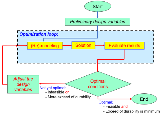
2.3. Optimization Algorithm for Structure Design
Figure 2. Flowchart of the optimization algorithm.
With the effective support of computers and simulation software, the author proceeds to develop an algorithm to calculate the optimal design for the dimensions of the structure. The essence of this is that the computer will automatically determine which components exceed the durability it will automatically decrease the thickness of those components, while the parts that lack durability it will automatically increase the thickness of those components. Unlike the conventional numerical simulation problem, which consists of only 3 stages of “modeling - solve - show results”, this computer program of optimal design will perform a series of sequential loops consisting of the following stages "- modeling - solve - evaluate results - remodeling - solve - " as the algorithm flowchart in
Figure 2.
3. Modeling of Structure
The beam tube heat exchange vessel in this study is a large structure with an overall length of 10000 (mm), an inner diameter of 1270 (mm). This heat exchanger consists of two compartments containing two different fluids, with different sizes and working conditions. It is made of SA516 Gr.70 steel
| [15] | ASME Boiler & Pressure Vessel Code, Section II, Part A, 2015, Edition. |
[15]
with properties in
Table 1, the chemical composition in
Table 2, and mechanical properties in
Table 3.
Table 1.
Properties of SA-516 Gr.70 steel | [15] | ASME Boiler & Pressure Vessel Code, Section II, Part A, 2015, Edition. |
Properties | SA-516M Gr.70 steel |
Young module (Pa) | E = 210*109 |
Density (kg/m3) | = 7800 |
Poisson coefficient | = 0.3 |
Allowable stress [] (MPa) | = 138.106 |
Table 2.
Chemical composition of SA-516 Gr.70 steel | [15] | ASME Boiler & Pressure Vessel Code, Section II, Part A, 2015, Edition. |
%C | %Mn | %Si | %S | %P |
0.27 0.28 | 0.79 1.3 | 0.13 0.45 | 0.035 | 0.035 |
Table 3.
Mechanical properties of SA-516Gr.70 steel | [15] | ASME Boiler & Pressure Vessel Code, Section II, Part A, 2015, Edition. |
Tensile strength (MPa) | Yield strength (MPa) | Elongation (%) |
200 mm | 50 mm |
485-620 | 260 | 17 | 21 |
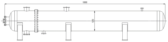
To ensure the desired volume, the length and inner diameter dimensions of the heat-exchange pressure vessel are kept constant. The design variables here consist of the thickness of the water chamber, the steam chamber, and the nozzles of these compartments. The preliminary design variables are arbitrarily chosen as follows:
1) Thickness of steam chamber: day1 = 12 mm
2) Thickness of water chamber: day2 = 25 mm
3) Thickness of nozzles in steam chamber: day3 = 15 mm
4) Thickness of nozzles in water chamber: day4 = 20 mm
The working conditions of this heat-exchange pressure vessel are taken according to the reality in the company, specifically as follows:
1) Maximum pressure in the water (liquid) chamber is 1.3 MPa.
2) Pressure in the steam (vapor) chamber is 0.45 MPa.
Figure 3. Structure diagrams of heat-exchange pressure vessel.
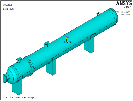
3.1. FEM Modeling of Heat-exchange Structure
This study uses the parametric design language (APDL) of ANSYS software to program according to the algorithm outlined in
Figure 2 with the above preliminary design variables to compute the optimal design of the heat-exchange pressure vessel as shown in
Figure 3. In order to be able to perform the loops with the aforementioned algorithm, the task blocks "modeling, solving, and results" must be written in the form of subroutines.
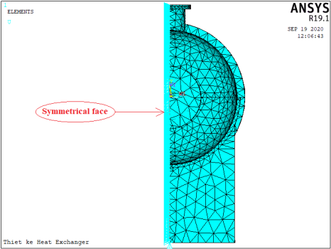
Because the 3D model has a symmetrical structure across the x-axis, to save computation time and storage space, the author only programs to build half of the model, then it will use the command to assign the symmetrical condition at this plane. When the program is running, the subroutine named “modeling” will automatically create and draw one half of the model as shown in the
Figure 4.
Figure 4. One half of 3D model of heat-exchange pressure vessel.
Since the heat-exchange pressure vessel is made in volumetric (3D) form and its structure has curved sides, to ensure accuracy when discretizing the model according to the finite element method, only the 3D element has a curved edge with triangular shape, as shown in
Figure 5, is suitable for the structure in
Figure 4.
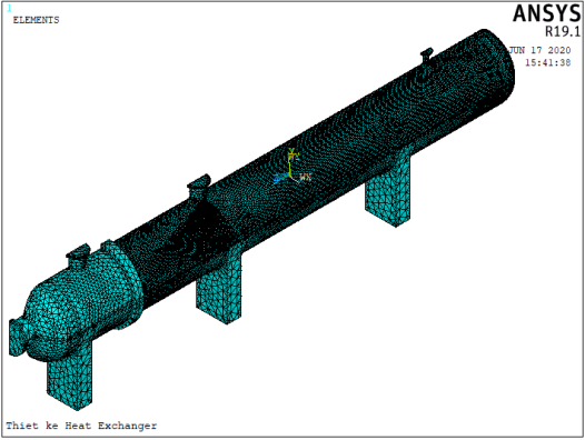
Different from the durability calculation in common numerical simulations, the optimal computation problem will continuously change the thickness of the model components at each calculation, so it is necessary to use an adaptive mesh. To achieve this, the computation program must use an automatic meshing method with a sufficiently fine mesh density. In this study, the written computer program used the SMRTSIZE (Smart Size) command of ANSYS APDL software to automatically generate the mesh. There are 10 levels of mesh, in which level 1 is the finest and level 10 is the coarsest. If the mesh is too coarse, the calculation will not converge, but if the mesh is too fine, it will take a lot of calculation time and computer storage capacity. For each size of the specific structure, there will be a suitable level of mesh, and it is determined by the test run process. In this problem, we found that level 6 is suitable for the researched heat-exchange pressure vessel.
Figure 6. FEM model of heat-exchange pressure vessel.
Figure 6 is the result of using the Solid92 element type to automatically mesh the 3D model in
Figure 4. With this meshing method, one half of the researched model (
Figure 6) has 890094 elements and 1813799 nodes.
3.2. Computation Conditions
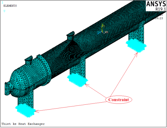
Figure 7. Boundary (constraint) conditions.
For the calculation of the durability of the structure, the boundary or constraint condition must be declared. In this study, the constraint condition of the model is the bolt connection between the base and the concrete foundation (
Figure 7). At these positions, the displacements in the directions are equal to 0 (Ux = Uy = Uz = 0).
Due to the symmetry of the model, it was built in half, but when calculating, we need to specify the position of the symmetry plane for the software to build the full matrix. The position of the symmetry plane in this study is shown in
Figure 8.
Figure 8. Symmetric conditions.
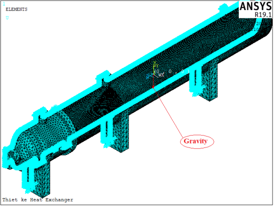
To calculate the effect of gravity on the structure, the program also automatically applies the acceleration of gravity on the structure as shown in
Figure 9.
Figure 9. Symmetric and gravity of the model.
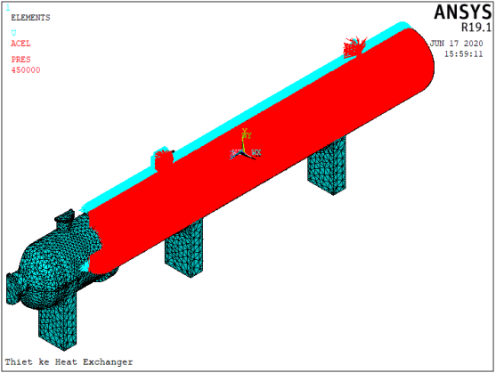
3.2.1. Apply the Pressure Load in the Vapor Chamber
In this structure, the vapor chamber contains steam, so the wall of the vapor chamber will be subjected to an even pressure equal to that of the steam (0.45 MPa). To apply a uniform pressure load in the vapor chamber, the computer program will automatically and accurately determine the inner surfaces of the vapor chamber. The results of applying the uniform pressure load on the wall of the vapor chamber are shown with the red arrows as shown in
Figure 10.
Figure 10. Uniform pressure in the vapor chamber.
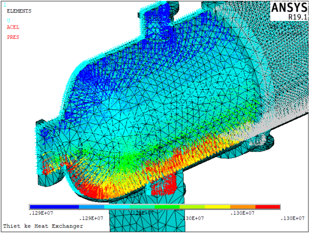
3.2.2. Apply the Pressure Load in the Water Chamber
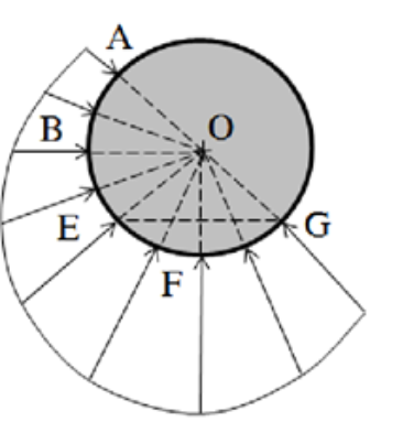
Because the water chamber is not filled with water but always has a small space above containing vapor with a certain residual pressure, so the application of pressure load in this water chamber will be divided into 2 parts are hydraulic pressure and uniform pressure.
Unlike a vapor chamber with uniform pressure, in the lower part containing liquid, the pressure acting on the wall of the water chamber is distributed according to the hydrostatic law as shown in
Figure 11.
Figure 11. Distribution of hydrostatic pressure on a curved surface.
The hydrostatic pressure of a liquid is determined by the formula: P = P0 + ρ.g.h
With: P0 is the residual pressure on the open surface of a liquid in the water chamber
ρ is the density of the liquid (density of water ρ=1000 kg/m3)
g is the acceleration of gravity (g=9.81 m/s2)
h is height of liquid column to open surface (m)
Under the working conditions of the heat exchanger in this study, the maximum water pressure acting on the water chamber is P = Pmax = 1.3 MPa - which is the pressure at the bottom of the water chamber. From the above equation, the pressure at the highest point in the water chamber is calculated as:
P0 = P - ρ.g.h = 1.300.000 – 1000*9.81*(2*0.625) = 1.287.737.5 (Pa)
When using the command to apply the hydrostatic pressure on the wall of the water chamber, we use the gradient method on the cylindrical coordinate system. The gradient coefficient in the cylindrical coordinate system is determined by the following formula:
= 270 is the Y coordinate in the cylindrical coordinate system of the point with maximum pressure (at the bottom of the water chamber).
= 90 is the Y coordinate in the cylindrical coordinate system of the original point.
Because according to the Y direction of the original coordinate system, the pressure decreases gradually, so the gradient has a negative value. Substituting numbers into the above formula will determine the value of the Gradient = -68.125.
Figure 12 is the result of applying the hydrostatic pressure load to the wall of the water chamber with a Gradient = -68.125, where the red vector represents the maximum pressure, and the blue vector represents the residual pressure acting on the wall above the open surface of the water chamber.
Figure 12. Hydrostatic and uniform pressure in the water chamber.
4. Computation Results & Discussion
4.1. Results of the Preliminary Design
Solving the system of matrix Eq. (
19) on the FEM space in
Figure 6 with the properties of the materials in
Table 1 by ANSYS APDL software, we obtained the results as shown in the following figures. The condition for the structure to be durable enough is: Seqv.max ≤ [σ] (with [σ] is allowing stress), but if Seqv.max ≪ [σ], the structure is too durable and wasteful of material.
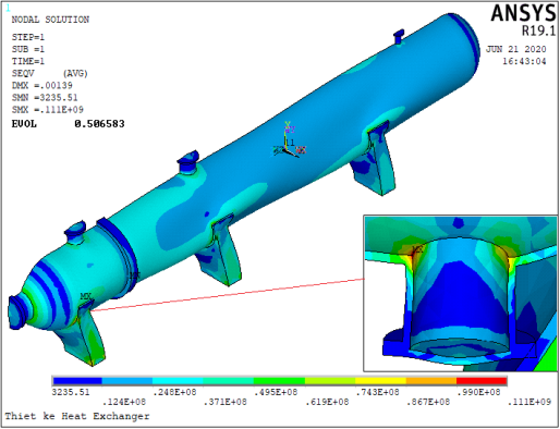
Figure 13. Von Mises Stress of preliminary design.
The computation results of the structure with the selected preliminary parameters (
Figure 13) show that the maximum equivalent (von Mises) stress located at the lower nozzle foot of the water chamber is Seqv.max = 111 (MPa) ≪ [σ] = 138.106 (MPa). This means that the structure is too durable that resulting in wastage of the materials. For the structure to be economical, to save materials and fabrication costs while ensuring the ability to work, it is necessary to redesign the structure.
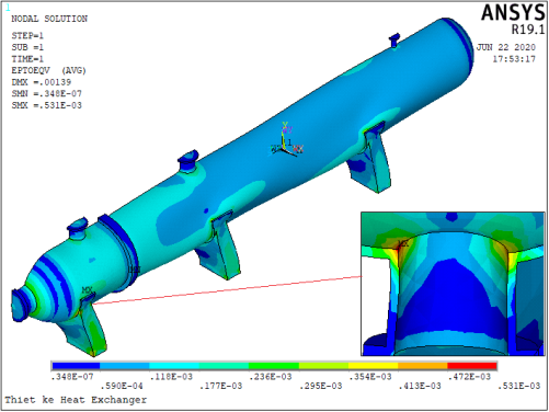
Figure 14. Total equivalent strain of preliminary design.
Figure 14 shows that the value of the total equivalent strain of the structure is located at the lower nozzle foot of the water chamber is 0.531 (mm).
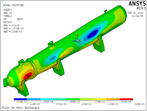
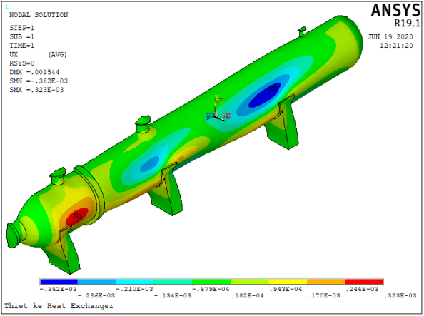
Figure 15. Displacement in the X direction of preliminary design.
In this preliminary design plan, the displacement of the structure in the X-direction under the loads is shown in
Figure 15, where the maximum value is 0.272 mm.
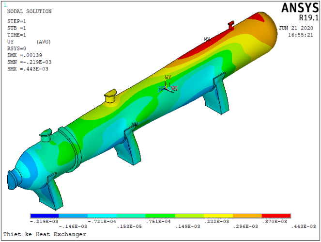
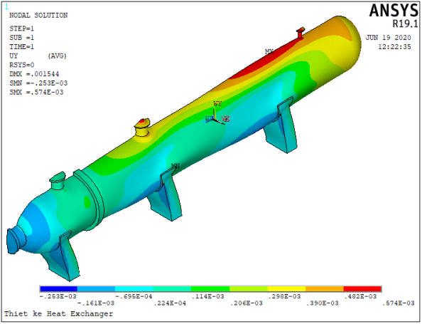
The displacement of the structure in the Y-direction under the loads is shown in
Figure 16, where the maximum value is 0.443 mm.
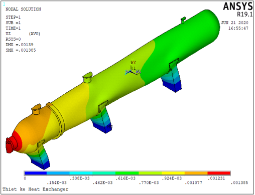
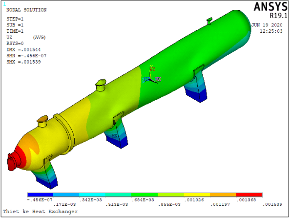
The displacement of the structure in the Z-direction under the loads is shown in
Figure 17, where the maximum value is 1.385 mm.
Figure 16. Displacement in the Y direction of preliminary design.
Figure 17. Displacement in the Z direction of preliminary design.
4.2. Results of Optimal Computation
After analyzing the structure in the preliminary design plan, the computer program will conduct the testing of the durability conditions in the parts of the structure. If any part has excess strength, then its thickness will be reduced in the next computation; and if any part lacks strength, then its thickness will be increased in the next calculation. The cycle of "modeling - solve - evaluate results - remodeling" is repeated until the maximum equivalent stresses on parts of the structure are close to allowable stresses then the program stops. The implementation of this algorithm will automatically find the optimal design plan (the design has the most reasonable shape, the most material savings, while ensuring the durability needed to work).
Figure 18. Results of optimal computation.
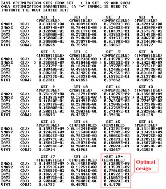
Results of running the program to optimize the shell structure of the heat-exchange pressure vessel are listed in
Figure 18. We easily see that of the feasible sets (1, 2, 4, 6, 9, 10, 13, 15, 16, and 19), the set 19 is the most compact of the feasible structures because the maximum equivalent stress in the vapor chamber (Smax1) and the maximum equivalent stress in the water chamber (Smax2) are both close to the allowable stress. It can be confirmed that it is the best design (optimal design) and will be used for production. Compared with the preliminary design plan, the volume of the structure has been reduced from Vtot = 0.50658 m
3 to Vtot = 0.41970 m
3, which means that 0.08688 m
3 or 677.664 kg of steel has been reduced.
However, since the calculated optimal dimensions are often odd numbers, so in fabrication, the manufacturer must choose them to follow the standard according to the principle that the selected dimensions must be equal to or greater than the calculated optimal dimensions. In this study, the dimensions of the selected design are chosen as follows:
Thickness of vapor chamber: day1 = 10 mm = day3
Thickness of water chamber: day2 = 20 mm = day4
From the calculated optimal dimensions combined with the standard as above, using the written computer program to re-check the strength of the structure, we obtained the results as shown in
Figures 19-23.
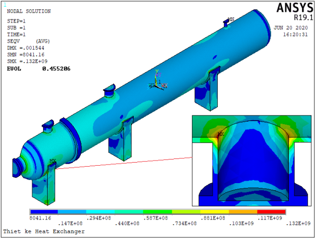
Figure 19. Von Mises Stress of selected design.
Figure 19 shows that the maximum equivalent (von Mises) stress is also located at the lower nozzle foot of the water chamber. Its value is Seqv.max = 132 [MPa] - smaller but close to the allowable stress ([σ]) of 138.106 (MPa). With this selected design, the volume of the structure was decreased from Evol = 0.506583 m
3 to Evol = 0.455206 m
3. That means that the selected design has ensured the structure is durable enough while saving 400,74 kg of steel.
Besides, the strain and displacement of the selected design will also be evaluated to compare with the initial plan.
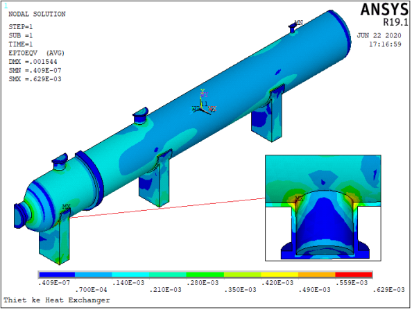
Figure 20 shows that the maximum total equivalent strain of the structure is 0.629 (mm), which is greater than the preliminary design value (0.531 mm).
Comparing the distribution morphology of equivalent stress, total equivalent strain, and displacement according to the directions between the preliminary design plan and the selected design, we find that these alternatives have similar distribution morphology each in terms of their respective quantities, but their values are different.
Figure 20. Total equivalent strain of selected design.
Figure 21. Displacement in the X direction of selected design.
Figure 22. Displacement in the Y direction of selected design.
Figure 23. Displacement in the Z direction of selected design.
Table 4. Displacement in X direction.
The maximum displacement | Preliminary design | Selected design |
Positive direction (mm) | 0.253 | 0.323 |
Negative direction (mm) | -0.272 | -0.362 |
Regarding the displacement according to the directions, the tables from 4 to 6 show that in the selected design the displacement in all directions is larger than the preliminary design in both positive and negative directions. This can be understood because the thickness of structural parts in the selected plan is less than that of the preliminary plan.
Table 5. Displacement in Y direction.
The maximum displacement | Preliminary design | Selected design |
Positive direction (mm) | 0.443 | 0.574 |
Negative direction (mm) | -0.219 | -0.253 |
Table 6. Displacement in Z direction.
The maximum displacement | Preliminary design | Selected design |
Positive direction (mm) | 1.385 | 1.539 |
Negative direction (mm) | 0 | |
5. Conclusions
The calculation for designing optimal structures has a crucial significance, it helps us not only to determine exactly the dimensions needed of the structural parts but also helps us to save a lot of fabrication material and costs. Compared with the preliminary design, which was too durable, the algorithm and computer program written in the APDL language of ANSYS software automatically determined the optimal design with a reduction of 677,664 kg of steel.
The new point of this article is the solution to automatically calculate to determine optimal dimensions of the structure by using numerical method, simulation software, and computer. With the new algorithm built, the designer can choose any preliminary design, but after a series of automatic computation loops, the computer will offer the best design for specific load conditions. This algorithm is not only used to calculate pressure equipment but can also be applied to any structure by modifying the computer program and changing the design variables.
Abbreviations
APDL | Ansys Parametric Design Language |
FEM | Finite Element Method |
ASME | The American Society of Mechanical Engineers |
Author Contributions
Toai Dinh Vu: Conceptualization, Data curation, Formal Analysis, Investigation, Methodology, Software, Writing – original draft.
Xuan Thi Tran: Project administration, Supervision, Validation, Validation, Visualization, Writing – review & editing.
Data Availability Statement
The data is available from the corresponding author upon reasonable request.
Conflicts of Interest
The authors declare no conflicts of interest.
References
| [1] |
Mayank Nirbhay, Prashant Tripathi, Vivek Kumar Gupta, “Implementation of ASME Codes to Design a Pressure Vessel and Toexplore the Influence of Various Design Parameters”, International Journal of Engineering Research & Technology (IJERT), 1014, 3(1), pp. 2497- 2504.
|
| [2] |
Thakkar, B. S., Thakkar, S. A., “Design of Pressure Vessel Using ASME Code, Section VIII, Division 1”, International Journal of Advanced Engineering Research and Studies, 2012, 1(3), pp. 228-234,
https://doi.org/10.21467/proceedings.4.33
|
| [3] |
Jegatheesan, J. and Zulkifli Zakaria, “Stress analysis on pressure vessel”, Environment & Ecosystem science, 2012, 2(2), pp. 53-57,
https://doi.org/10.26480/ees.02.2018.53.57
|
| [4] |
Parkhe, S., Annamalai, K., “Design and Analysis of Pressure Vessel Subjected to Pressure-temperature Variation”, International Journal of Engineering, IJE Transactions A: Basics, 2018, 31(1), pp. 58-64,
https://doi.org/10.5829/ije.2018.31.01a.09
|
| [5] |
Niranjana, S. J., Smit Vishal Patel, Ankur Kumar Dubey, “Design and Analysis of Vertical Pressure Vessel using ASME Code and FEA Technique”, IOP Conf. Series: Materials Science and Engineering, 2018, 376, 012135.
https://doi.org/10.1088/1757-899X/376/1/012135
|
| [6] |
Rafiq Rustam, Ahmad Faiz Ahmad Nazri, Md Rizal Md Tasliman, and Jamaluddin Mahmud, “Finite Element Simulation and Analysis for the Design of a Pressure Vessel with Expansion Joint”, International Journal of Materials, Mechanics and Manufacturing, 2018, 6(4), pp. 268- 272,
https://doi.org/10.18178/ijmmm.2018.6.4.389
|
| [7] |
Farid Ahmed, Md Minaruzzaman Sumon, Muhtasim Fuad, Ravi Gugulothu, AS Mollah, “Numerical Simulation of Heat exchanger for analyzing the performance of parallel and counter flow”, WSEAS Transactions on Heat and Mass Transfer, Volume 16, 2021, pp. 145-152,
https://doi.org/10.37394/232012.2021.16.17
|
| [8] |
Vishal V. Saidpatil, Arun S. Thakare, “Design & Weight Optimization of Pressure Vessel Due to Thickness Using Finite Element Analysis”, International Journal of Emerging Engineering Research and Technology, 2014, 2(3), pp. 1-8.
|
| [9] |
Arun Kumar, M. H., Manjunath, S., Amith Kumar, S. N., “Design of pressure vessel using ASME codes and a comparative Analysis using FEA”, International Research Journal of Engineering and Technology (IRJET), 2017, 4(11), pp. 617- 625.
|
| [10] |
Jie Dou, Fude Wang, “Simulation study on optimization design of small gas water heat exchangers”, Journal of Physics: Conference Series 2835 (2024) 012070, Volume 2835, pp. 1-6,
https://doi.org/10.1088/1742-6596/2835/1/012070
|
| [11] |
Zengliang Chen, Ye Luo, Zhihui Wang, Yulin Liu, Limei Gai, Qichao Wang and Bingyuan Hong, “Optimization Design and Performance Study of a Heat Exchanger for an Oil and Gas Recovery System in an Oil Depot”, Energies 2024, 17, 2631.
https://doi.org/10.3390/en17112631
|
| [12] |
Juanjuan Wang, Jiangping Nan and Yanan Wang, “CFD-Based Optimization of a Shell-and-Tube Heat E xchanger”, Fluid Dynamics & Materials Processing, FDMP, 2023, vol. 19, no. 11, pp. 2761-2775,
https://doi.org/10.32604/fdmp.2023.021175
|
| [13] |
Chongyang Wang, Weiting Jiang, Weiguo Pan, Tingni He, “Structure Optimization and Numerical Simulation of Micro Gas Turbine Regenerator”, Journal of Physics: Conference Series, Volume 2296 (2022) 012005, pp. 1-6,
https://doi.org/10.1088/1742-6596/2296/1/012005
|
| [14] |
ANSYS Inc., Theory reference for the ANSYS and Workbench Product, 2018, Version 19.1.
|
| [15] |
ASME Boiler & Pressure Vessel Code, Section II, Part A, 2015, Edition.
|
Cite This Article
-
APA Style
Vu, T. D., Tran, X. T. (2025). Design Optimization of the Heat-exchange Pressure Vessel by Numerical Simulation Analysis. International Journal of Materials Science and Applications, 14(3), 89-105. https://doi.org/10.11648/j.ijmsa.20251403.15
 Copy
|
Copy
|
 Download
ACS Style
Vu, T. D.; Tran, X. T. Design Optimization of the Heat-exchange Pressure Vessel by Numerical Simulation Analysis. Int. J. Mater. Sci. Appl. 2025, 14(3), 89-105. doi: 10.11648/j.ijmsa.20251403.15
Copy
|
Download
AMA Style
Vu TD, Tran XT. Design Optimization of the Heat-exchange Pressure Vessel by Numerical Simulation Analysis. Int J Mater Sci Appl. 2025;14(3):89-105. doi: 10.11648/j.ijmsa.20251403.15
Copy
|
Download
-
@article{10.11648/j.ijmsa.20251403.15,
  author = {Toai Dinh Vu and Xuan Thi Tran},
  title = {Design Optimization of the Heat-exchange Pressure Vessel by Numerical Simulation Analysis
},
  journal = {International Journal of Materials Science and Applications},
  volume = {14},
  number = {3},
  pages = {89-105},
  doi = {10.11648/j.ijmsa.20251403.15},
  url = {https://doi.org/10.11648/j.ijmsa.20251403.15},
  eprint = {https://article.sciencepublishinggroup.com/pdf/10.11648.j.ijmsa.20251403.15},
  abstract = {Currently, the thickness of the elements of pressure vessels is often determined by calculation according to the formulas in ASME Code Section VIII or numerical simulation using mechanical calculation software. Calculations according to the ASME Code often give results with much excess durability, while conventional numerical simulation calculations will take a lot of time due to manual detection and depend heavily on the experience of the designer. Both of the above methods are very difficult to determine the optimal value of design variables (thickness of the structure) to ensure the most workability and material savings. This paper presents an automatic calculation method to determine the optimal thickness of the elements of a pressure vessel through a new self-developed simulation algorithm, in which all the stages of a conventional numerical simulation problem have been wrapped into an automatic loop “– modeling – solve – evaluate results – remodeling –”. A computer program written in the APDL language of ANSYS software, based on this new algorithm, has automatically determined the optimal value of the thicknesses of the pressure vessel regardless of its initially selected preliminary values. That is, starting from any preliminary value of the design variables, the computer program will automatically calculate to determine the optimal value of the design variables that ensure the structure satisfies the working conditions and has the smallest mass or volume. Applying this method, the volume of the considered heat-exchange pressure vessel was reduced from 0.50658 m3 to 0.41970 m3, which means that 0.08688 m3 or 677.664 kg of steel was saved.
},
 year = {2025}
}
Copy
|
Download
-
TY  - JOUR
T1  - Design Optimization of the Heat-exchange Pressure Vessel by Numerical Simulation Analysis

AU  - Toai Dinh Vu
AU  - Xuan Thi Tran
Y1  - 2025/06/23
PY  - 2025
N1  - https://doi.org/10.11648/j.ijmsa.20251403.15
DO  - 10.11648/j.ijmsa.20251403.15
T2  - International Journal of Materials Science and Applications
JF  - International Journal of Materials Science and Applications
JO  - International Journal of Materials Science and Applications
SP  - 89
EP  - 105
PB  - Science Publishing Group
SN  - 2327-2643
UR  - https://doi.org/10.11648/j.ijmsa.20251403.15
AB  - Currently, the thickness of the elements of pressure vessels is often determined by calculation according to the formulas in ASME Code Section VIII or numerical simulation using mechanical calculation software. Calculations according to the ASME Code often give results with much excess durability, while conventional numerical simulation calculations will take a lot of time due to manual detection and depend heavily on the experience of the designer. Both of the above methods are very difficult to determine the optimal value of design variables (thickness of the structure) to ensure the most workability and material savings. This paper presents an automatic calculation method to determine the optimal thickness of the elements of a pressure vessel through a new self-developed simulation algorithm, in which all the stages of a conventional numerical simulation problem have been wrapped into an automatic loop “– modeling – solve – evaluate results – remodeling –”. A computer program written in the APDL language of ANSYS software, based on this new algorithm, has automatically determined the optimal value of the thicknesses of the pressure vessel regardless of its initially selected preliminary values. That is, starting from any preliminary value of the design variables, the computer program will automatically calculate to determine the optimal value of the design variables that ensure the structure satisfies the working conditions and has the smallest mass or volume. Applying this method, the volume of the considered heat-exchange pressure vessel was reduced from 0.50658 m3 to 0.41970 m3, which means that 0.08688 m3 or 677.664 kg of steel was saved.

VL  - 14
IS  - 3
ER  -
Copy
|
Download