Research Article | | Peer-Reviewed

Development and Experimental Evaluation of a New Photovoltaic-thermal Air Collector to Optimise the Performance of PV Solar Modules

Received: 8 January 2026     Accepted: 20 January 2026     Published: 6 February 2026
Views:       Downloads:
Abstract

One of the main challenges to the performance of photovoltaic (PV) modules is the reduction in efficiency resulting from their high working temperature. Air-based photovoltaic/thermal (PV/T) devices offer a solution. This work presents the development of a photovoltaic/thermal air heat collector to optimize the performance of PV modules: Experimental case with monocrystalline and polycrystalline silicon photovoltaic solar modules. This was accomplished by designing, constructing, and positioning a thermal collector under the solar modules that had a surface area of 0.378 m2 and a height of 0.11 m. A real-time experimental study conducted on a sunny day in the courtyard of ISABEE of university of Ebolowa, Cameroon, showed that the proposed collector maintained the temperature below the monocrystalline solar panel at 49°C and that of the polycrystalline panel at 51°C, respectively, in order to an average power of 56.24 W (a power gain of 9 W compared to conventional PV) for the monocrystalline panel and 62.4 W (a power gain of 18 W) for the polycrystalline panel. DC fans where set up at the collector’s outlet were used to control the air flow rate to optimize cooling. In terms of thermal performance, a power output of 242 W (52% efficiency) was achieved for the monocrystalline module, while the polycrystalline module reached 295.94 W (56.46% efficiency). The tests, conducted under average sunlight of 936.36 W/m2 (between nine in the morning and three in the afternoon), demonstrated the system's efficiency. This study not only validates the optimization of electrical and thermal performance using the proposed technique, but also reveals the different behavior of the two types of cells. This collector can be considered highly suitable for optimizing the efficiency of PV modules in domestic solar installations, particularly in regions with an equatorial climate (such as the southern region of Cameroon) and high ambient temperatures.

Published in International Journal of Sustainable and Green Energy (Volume 15, Issue 1)
DOI 10.11648/j.ijsge.20261501.14
Page(s) 31-44
Creative Commons

This is an Open Access article, distributed under the terms of the Creative Commons Attribution 4.0 International License (http://creativecommons.org/licenses/by/4.0/), which permits unrestricted use, distribution and reproduction in any medium or format, provided the original work is properly cited.

Copyright

Copyright © The Author(s), 2026. Published by Science Publishing Group

Keywords

Heat Collector, Cooling, Types of Solar Modules, Hybrid PV/T Solar Air System, Energy Savings, Optimization

1. Introduction
With growing global energy demand, photovoltaic (PV) modules have established themselves as an essential solution for electricity generation in both residential and commercial applications . These semiconductor devices directly convert solar radiation into electricity, offering a clean and inexhaustible energy source. However, their conversion efficiency remains a major challenge. For dominant silicon-based technologies, the electrical efficiency is generally below 23%, while multi-junction cells reach approximately 40% . Consequently, a considerable portion of the incident solar radiation is not converted into electricity but is instead dissipated as heat, which increases the cells' operating temperature and significantly degrades their electrical efficiency .
To mitigate this limitation, various cooling strategies have been developed, including active techniques (air or liquid cooling) and passive techniques (phase change materials, heat exchangers) . Among these approaches, hybrid photovoltaic/thermal (PV/T) technology, which has been studied for several years stands out for its dual benefit: it not only cools the PV module to optimize its electrical output but also recovers the extracted heat for thermal systems .
PV/T systems are generally divided into two types: unglazed collectors, which prioritize higher electrical performance by producing heat at a lower temperature, and glazed collectors, which generate heat at elevated temperatures but have a bit less electrical performance . Although water-based PV/T systems provide excellent cooling, their implementation can be more complex than that of conventional panels . Air-based systems, meanwhile, represent a robust and simpler alternative to integrate.
A significant body of research explores various cooling techniques to improve PV module performance. For instance, Yang et al simulated the impact of pre-cooling the air with a dew point evaporative cooler, concluding an efficiency improvement of 16.4% compared to conventional air cooling. Other works have conducted comparative experimental studies . Fatih Bayrak et al evaluated phase change materials (PCM), thermoelectricity (TE), and aluminum fins, finding that the fins provided the greatest power gain (47.88 W) and noting that an improperly selected PCM could even have a counter-productive insulating effect . More broadly, Nizetic et al quantified the potential for efficiency improvement by technique, with gains reaching up to 20% for air, 21.2% for PCM, and 22% for liquids. In their experimental investigation of enhanced performance solar cell panels with air conditioners that use fins and materials with phase changes on the rear plate . Harish et al demonstrated that the suggested model permits a temperature drop of 9.5 to 14°C in the front of the panel relative to the panel itself. On average, there was a 15.5% improvement in both electrical performance and power production .
Beyond the cooling method, the choice of PV cell technology is also a determining factor. The study by Toto et al is particularly insightful in this regard. By comparing monocrystalline and polycrystalline modules (without active cooling), they observed that the polycrystalline module produced higher power output during hours of high irradiance and elevated temperatures. This result suggests that the relative performance of these two technologies could be differently influenced by a cooling system . In particular, Natalie et al.'s work on air-based PV/T systems shown that design parameters like duct depth and air velocity were crucial optimization levers in addition to demonstrating that an air duct may increase the electrical efficiency of the PV module (a gain of 13.67%) .
While extensive research exists on air-based PV/T systems and on the comparison of solar panels, few studies have conducted a direct and systematic experimental comparison of the performance of monocrystalline and polycrystalline technologies within the same forced-air PV/T architecture.
The purpose of this study is to close this gap. We planned, constructed, and tested a hybrid photovoltaic-thermal system in which heat is drawn from beneath the modules by a collector and expelled by forced ventilation. The main objective is to optimize the electrical power of monocrystalline and polycrystalline solar modules by regulating their operating temperature. To do this, we developed a heat collector model and then analyzed and compared the evolution of sunlight, temperatures, electrical power, and yields for each technology in simple PV and PV/T configurations.
2. Materials and Methods
2.1. Hybrid PV/T Air System Design
Combining the two uses of heat and electricity is the idea behind a hybrid photovoltaic-thermal collector. In this type of hybrid component, air circulation at the back cools the PV cells. Figure 1 show the heat collector designed in SOLIDWORKS. A PV solar module, a heat collector that is thermally insulated, and a fan that draws hot air from the collector and blows it into the drying or heating area make up the system. The fan draws heat when the temperature under the collector is high enough.
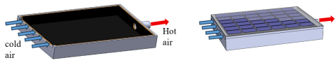
Figure 1. Heat collector designed in solidworks.
2.1.1. Surface Area of the Air Heat Collector
The solar module's length L and width l determine the heat collector's surface area. Rectangular silicon solar modules were selected for this project. We have:
S= L×l(1)
Where S is the solar panel's surface area (m2); L is the length (m) of the module and l is the width (m).
2.1.2. Collector Box
We will design the air thermal collector that will be placed under the PV solar module to collect heat. The relevant parameters for efficiency are: The width (l) of the sensor, because the temperature of the fluid varies according to the width. The photovoltaic solar module. The air velocity, V, since velocity is a parameter that makes it possible to utilize fluid mechanics to examine the air's behavior in the collector. This variable also affects the transmission between the heat transfer fluid and the back of the PV cells. Determining the air flow velocity in rectangular ducts hang on the flow regime considered by the Reynolds number, defined by :
Re=ρ×Vv×Dhμ (2)
Where: Re is the Reynolds number, ρ is the density (kg/m³), μ is the dynamic viscosity of the flowing fluid (kg/ms), Vv is the average flow velocity in the effective air flow duct (m/s), and Dh is the equivalent hydraulic diameter of the effective duct (m), given by the formula (3) :
Dh=4SCPm(3)
Where SC Cross-sectional area of the collector's air inlet (m2); Pm wet perimeter.
The collector contains a small thickness (e) between the aluminum sheet and the back of the solar panel. The upper part of the collector has a hole for attaching the fan.
2.1.3. Collector Insulation
An essential part of the collector's design is the insulating unit. Its purpose is to reduce heat loss from the collector's sides, back, and front. Several insulating materials have been used to lessen heat loss at the back of flat-plate collectors. Thus, the selection of thermal insulation is contingent upon its capacity to provide a particular degree of energy efficiency. We can determine the thermal resistance using the following formula (4), which accounts for the insulation's thickness and thermal conductivity.
R=eλ(4)
Where: R is thermal resistance (m2.K/W); e is insulation thickness (m); λ is thermal conductivity coefficient (W/m.K).
The collector needs to be properly insulated using the right materials. To reduce heat loss by conduction over the collector surfaces, these materials need to have low thermal conductivity.
Using formula (4), we can determine the thickness of the insulation and its thermal resistance. Generally, the thickness of the insulation is between 3 and 10 cm. Insulating materials often consist of mineral wool and synthetic materials like glass wool, polyurethane, or polystyrene foam. The extreme temperatures that can occur inside a collector must be tolerated by them.
2.1.4. Choice of Absorber
The quality of a collector is significantly impacted by the material used and construction approach. The most widely utilized materials are copper, steel, and aluminum because of their great conductivity.
A selective layer is typically applied to absorbers to minimize radiation losses. In the majority of collectors, nickel and chromium are the primary metals utilized for selective coatings.
2.1.5. Fan Selection
Cold outside air is drawn into the collector and blown into the heating area by a centrifugal fan, located downstream of the collector and connected to the internal frame by an airtight duct.
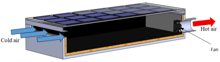
Figure 2. Longitudinal section of the manifold ventilation.
The characteristics (electrical power) of the fan will be determined using formula (5) below:
Pv=P×Qηv×3600(5)
Where: Pv is the electrical power of the fan (W); Q is the fluid flow rate (m3/h); P is the equivalent pressure (in Pa or N/m2); ηv is the overall efficiency of the fan.
The air flow rate Q is determined by the fan using the air velocity and the air inlet cross-sectional area. This flow rate is calculated using equation (6).
Q=Vv×SC(6)
Where:
Vv is the average wind speed at the collector inlet (m/s); Q is the air flow rate (m3/s) and SC is the air inlet cross-sectional area (m2) or SC= l×e (where l is the width of the collector and e is the thickness of the air inlet).
The equivalent pressure is obtained using the general Darcy-Weisbach formula defined by the following formula (7):
P=γVv22g(LDh )(7)
Where:
Vv: pipe’s average flow velocity in m/s;
Dh: hydraulic diameter of the channel in m (Dh = 4Sc/Pm where S is the cross-sectional area and Pm is the wet perimeter);
L: length of the pipe in m; g acceleration due to gravity in m/s2.
γ: specific weight of the fluid conveyed in kg/m3.
2.2. Heat Transfer and Equations in the PV/T Air Heat Collector
Conduction, convection, and radiation are the three heat transmission mechanisms that are all involved in the system at the same time. In this case, we will focus on convective transfers in the collector.
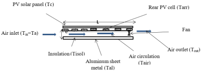
Figure 3. Diagram of the different heat exchanges on the PV/T air collector.
Heat transfer by convection in the collector
Air, the heat transfer fluid, absorbs some energy as it moves through the collector through convection, partly from the aluminum sheet and partly from the back of the solar module, enabling it to store what is known as “useful” heat. The following is the equation that governs heat transfer in the hybrid collector :
Qu=hAl-air TAl-Tair +hair -arr PVTair - Tarr PV (8)
With:
Qu Amount of useful heat stored (W/m2); hAl-air  Convective transfer coefficient between aluminum sheet and fluid (W/m2 °C); hair -arr PV Convective transfer coefficient between fluid and rear of PV cells (W/m2 °C); TAl Temperature of the aluminum sheet; Tair  Temperature of the collected air and Tarr PV Temperature at the rear of the solar panel.
For convective exchange between the solar panel's back and the heat transfer fluid, we have:
hAl-air =hair -arr PV
Convective heat transfer between the aluminum sheet and the solar module.
Heat transfer in the space between the back of the solar panel and the aluminum sheet is characterized by convective exchange. To determine the internal convective heat transfer coefficient (hair -arr PV) in the case of rectangular ducts, we use the correlations defined by Sieder and Hausen:
harr pv-air =Nu×λaDh(9)
With:
harr pv-air Convection transfer coefficient between the rear of the solar panel and the air; Dh Hydraulic diameter (m); λa Thermal conductivity of the air gap behind the solar panel and Nu Nusselt number.
The fluid's temperature, velocity, and geometric properties of the solid/fluid contact surface all affect the convective heat transfer coefficient's value.
The determination of the internal convective heat transfer coefficient (harr pv-air) in the case of rectangular ducts depends on the flow regime characterized by the Reynolds number. In smooth turbulent flow, the Nusselt number is estimated by the following correlation defined by (Kays and Crawford).
Nu=0,6Re0,5Pr0,31(10)
Where,
Nu is the Nusselt number; Re is the Reynolds number and Pr is the Prandtl number,
Pr=μCPλ(11)
With:
Cp specific heat (J/kg K) For air Cp = 1006 J/kg K; 𝝁 dynamic viscosity of air (kg/m.s) and λ thermal conductivity coefficient of air (W/m. °C).
2.3. Construction of the PV/T Air Collector
The experimental device was constructed to enable analysis of the performance of the proposed collector. It consists of four 50 Wp photovoltaic modules (ENSKY SOLAR brand), mounted on the same support at an angle of 3° to the horizontal.
Two modules (one monocrystalline and one polycrystalline) were integrated with an air-cooling system to operate in PV/T mode.
Two identical modules (one monocrystalline and one polycrystalline) were left in a standard configuration, without active cooling, to serve as reference modules.
This comparative approach, contrasting the proposed air-cooled PV/T model with a reference PV system under strictly identical sunlight and ambient temperature conditions, is widely adopted in the literature to unambiguously isolate the effect of cooling on electrical and thermal performance . The technical characteristics of the modules are presented in Tables 1 and 2.
Table 1. Monocrystalline module characteristics.

Module type

class A 12V

Maximum Power

50W

Current at Maximum Power

2,78A

Voltage at Maximum Power

18

Short-Circuit Current

3,38A

Open-Circuit Voltage

21,7V

Nominal Operating Cell Temperature

25ºC

Maximum Surface Load

700N/m2

Cells in Series

12

Weight

3 kg

Dimensions

700 x 540 x 40 mm

Table 2. polycrystalline module caracteristics.

Module type

class A 12V

Maximum Power

50W

Current at Maximum Power

2,54A

Voltage at Maximum Power

18V

Short-Circuit Current

3,06A

Open-Circuit Voltage

21,7V

Nominal Operating Cell Temperature

25ºC

Maximum Surface Load

700N/m2

Cells in Series

12

Weight

3 kg

Dimensions

700 x 540 x 40 mm

The figures below show the monocrystalline and polycrystalline PV solar panels.
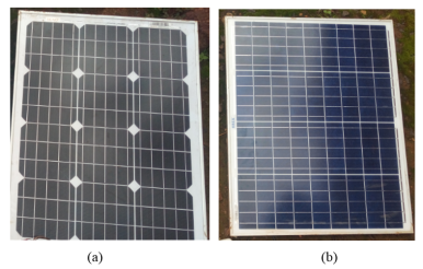
Figure 4. (a) monocrystalline PV solar pannel (b) polycrystalline PV solar panel.
Construction of the Heat Collector
A thermal collector was manufactured and integrated under the rear surface of each PV module. The collector design, consisting of a forced air circulation channel under an unglazed PV module, is a classic and proven configuration for air-based PV/T systems, recognized for its simplicity and effectiveness in improving electrical efficiency .
1) Air circulation channel: The box (70 cm x 54 cm x 11 cm) was made of aluminum sheet metal (1.5 mm thick).
2) Collector insulation: The underside was thermally insulated with a polyurethane foam plate to minimize heat loss to the environment.
3) Thermal Absorber: A thin sheet of aluminum, painted matte black, was attached to the inside of the duct, just below the PV module. The blackened sheet serves to increase the emissivity of the surface and promote radiative heat transfer between the rear of the PV module and the circulating air. An electric fan (axial type, DC powered) was installed at the outlet of the channel to operate in extraction mode. This configuration ensures forced air circulation, drawing ambient air through the channel inlet and evacuating heated air, thus regulating the temperature of the PV module.
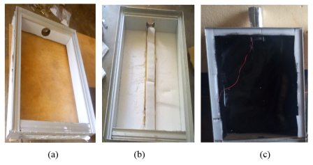
Figure 5. (a) Collector box (b) Collector insulation (c) Absorber and fan.
2.4. Instrumentation and Data Acquisition
To ensure the reliability of the measurements, the test bench was equipped with the following instruments:
1) Solar Irradiance: A solar power meter (model FI-109SM) was mounted in the plane of the modules to measure the global solar irradiance (G) in W/m2. It has a measuring range of up to 1 999 W/m² or 634 BTU/(ft² × h) with a typical accuracy of ±5% to ±10% of the reading for portable devices in this category (or ±10 W/m²).
2) Temperatures: Temperature sensors (model DHT22) were used to measure: the ambient temperature (Ta), the rear surface temperature of each module (Tpv), and the air temperature at the inlet (Tin) and outlet (Tout) of the thermal collectors. It has a wide measuring range (-40°C to 80°C / 0-100% RH), good accuracy (±0.5°C / ±2% RH), and resolution of 0.1°C/0.1% RH.
3) Electrical Performance: For each module, voltage (V) and current (I) sensors were used to continuously monitor the electrical output under load. We have chosen the ACS7250 current transducer because it can measure direct currents up to 50 A. Connected in series with the load, it uses the magnetic field generated by the current (and therefore the hall effect) to measure the current flowing through it.
4) Data Acquisition: A centralized data acquisition module was used to log all parameters at 10-minute intervals during the testing days (from 9:00 AM to 3:00 PM).
2.5. Experimental Site
The study was conducted under real climatic conditions on the campus of the ISABEE at the University of Ebolowa, located in the South Cameroon region (latitude: 3°32'0'' N; longitude: 11°32'0'' E; altitude: 629 m). This location, characterized by an equatorial climate, has high solar potential but also high ambient temperatures, making the issue of PV module cooling particularly relevant.
2.6. Assessment of the Air-based PV/T System's Performance
2.6.1. Electrical Performance Evaluation
The following formula is used to determine the solar module's maximum electrical power (Pmax) :
Pmax=Vmax×Imax(12)
With:
Pmax Maximum Power (W); Imax Current at Maximum Power A and Vmax Voltage at Maximum Power (V).
Instantaneous and daily assessments of the module's electrical efficiency were conducted.
Instantaneous Efficiency
The ratio of the maximum power production to the incident solar power on the module surface area of the is known as the instantaneous electrical efficiency (η_e), using Equation (13) :
ηe=Pmax S× G(13)
With:
ηe Instantaneous electrical efficiency (%); Pmax Maximum power output (W); S Module’s surface area of the (m2) and G Instantaneous global solar irradiance (W/m2).
Daily Efficiency
The average daily efficiency (ηj) provides an overall performance indicator for a given day. It is calculated using the average power and average irradiance values over the measurement period:
ηj=PmaxGm(14)
Where:
ηj Average daily efficiency (%); Pmax Maximum power output (W); S Surface area of the module (m2) and Gm Average solar irradiance over the day (W/m2).
2.6.2. Thermal Performance Evaluation
(i). Determining the Thermal Power of the Collector
The useful thermal power (or heat gain) extracted by the air flowing through the collector is given by the following equation :
PT=ṁ×CP(Tout-Tin)
This can also be expressed using the volumetric flow rate:
PT=ρair×CP×Q(Tout-Tin)(15)
Where:
PT Useful thermal power (W); ṁ Mass flow rate of air (kg/s); Tin Inlet air temperature (assumed to be the ambient temperature, Ta) (°C); Tout Outlet air temperature (°C); CP Specific heat of air (J/kg·°C); Q Volumetric flow rate of air (m3/s); ρair Density of air (Kg/m3).
(ii). Determination of the Thermal Collector's Efficiency
Efficiency, which takes into consideration the thermal energy gained in relation to the incident solar energy, is what defines the collector's thermal performance. To provide a more rigorous evaluation, the electrical power consumed by the fan is subtracted from the useful thermal power, yielding a net thermal efficiency.
Instantaneous Thermal Efficiency
The following relationship defines the instantaneous thermal efficiency (η_th) :
ηth=ρair×CP×Q(Tout-Tin)×  S+ Pv(16)
Where:
ηth Instantaneous thermal efficiency (%); S Surface area of the module (m2); G Average solar irradiance over the day W/m2) and Pv Electrical power consumed by the fan (W).
Daily Thermal Efficiency
Using the average values over the measurement time, the daily average thermal efficiency (η_d) is computed:
ηd=PTPv+ S Gm(17)
Where:
ηd Average daily thermal efficiency (%); Pv Electrical power consumed by the fan (W); S Surface area of the module (m2) and Gm Average solar irradiance over the day (W/m2).
3. Results and Discussions
The impacts of the collector design and the experimental findings from the PV/T air heat collector are shown and discussed in this section.
3.1. Characteristics of the Thermal Collector
The surface area of the sensor is 0.378 m2, after setting the air inlet in the collector at 0.015 m and the average wind speed in Ebolowa at 1 m/s. We had a Reynolds number of Re=2167 which corroborates the work of Sail et al, where they obtained better collector performance with Reynolds numbers between 1600 and 6000, the thermal conductivity of air is λ=0.3W.m-1.K-1, and the hydraulic diameter Dh=0.11 m, which is the height of the air channel of the thermal collector placed below the solar panel for heat collection. This air channel height is within the range of different optimal heights proposed by Mohammad et al. in their work, where they investigated how air channel height affected collector efficiency. Formula (4) states that polyurethane foam, which has a thermal resistance of R=2.01 m2.K/W, is the thermal insulation, so the thickness is set at 3 cm. This thermal resistance value varies depending on the thickness of the material; the greater the thickness, the better the collector will be thermally insulated. By setting the overall efficiency of the fan at 75%, its power is 1.01W here are the actual specifications (12V DC; 1W; 56m³/h), which is not energy-intensive and allows heat to be removed from the collector to regulate the temperature below the PV modules. The pressure ∆P=11Pa, which is likewise a function of the air channel, was taken into consideration while calculating this fan power using formula (7). The larger the air channel, the greater the fan power, which is not recommended. The result of the design of the PV/T air heat collector using SolidWorks computer-aided design software can be seen in Figure 6 below.
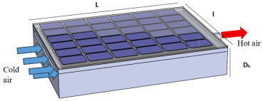
Figure 6. Air PV/T system designed in SOLIDWORKS.
Figure 7 below shows an overview of the air PV/T system that was built. It consists of monocrystalline and polycrystalline photovoltaic solar modules with an air collector underneath and monocrystalline and polycrystalline reference modules. This experimental device was used for the measurements.
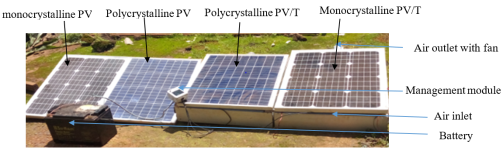
Figure 7. Experimental device constructed.
3.2. Data Acquisition and Control System
The Figure 8 below shows a view of the electronic control board of the system constructed and placed in a box for measuring temperature, current, and voltage. It has a number of electronic parts, including the ATMEGA328P microcontroller; relays; diodes (1N4001); resistors; the RTC (real-time clock); current (ADA4226) and voltage (FO31-06) sensors; and the LCD display. Data was acquired every ten minutes and recorded on an SD card.
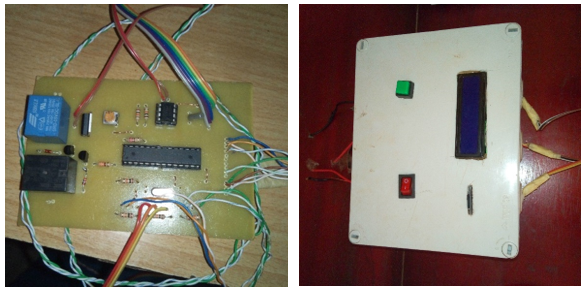
Figure 8. Data acquisition and management module.
3.3. Experimental Results for the PV/T Air Heat Collector
We present an analysis of the experimental data collected at the University of Ebolowa site. The results discussed below correspond to a representative test day, April 25, 2025, characterized by strong sunlight (average of 936.36 W/m2 with a peak of 1219 W/m2), ideal conditions for evaluating overheating phenomena and the efficiency of the proposed collector.
3.3.1. Analysis of Collector Performance with Monocrystalline PV Modules
The analysis focuses on the monocrystalline and polycrystalline modules in three distinct configurations: reference PV, non-ventilated PV/T, and PV/T with active cooling.
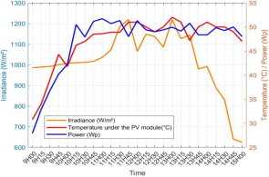
Figure 9. Performance of the reference monocrystalline PV module.
Figure 9 exposes the baseline behavior of the standard photovoltaic module. A direct yet antagonistic correlation is observed between temperature and useful power output.
Thermal Profile: The module's rear surface temperature closely follows the irradiance curve, rising from 30°C in the early morning to a peak temperature of 51°C at 12:30 PM. The thermal rise observed is a direct consequence of the substantial conversion of incident solar energy into thermal energy.
Electrical Profile and Degradation: The electrical power reaches a maximum of 51.7 W at 11:00 AM. However, past this point, even as solar irradiance continues to increase towards its zenith, the power output stagnates and then declines. This phenomenon, known as thermal degradation, illustrates the negative impact of the module's temperature coefficient. The accumulated heat hampers electrical performance, limiting the module's average daily power output to 45 W.
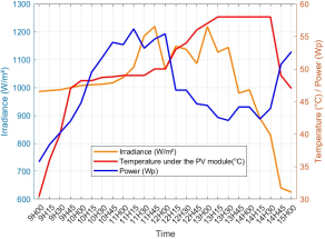
Figure 10. Performance of the monocrystalline PV/T module without cooling.
Figure 10 highlights a fundamental and counter-intuitive result. When the module is mounted on the thermal collector without activating the ventilation, the system becomes a heat trap. The casing, by confining the air, creates a localized greenhouse effect. The module's rear surface temperature soars to 58°C, which is 7°C higher than the reference module freely exposed to the air. This severe overheating has a devastating effect on electrical production. The average daily power output plummets to 44 W.
This experiment demonstrates a critical point: a poorly managed PV/T design, where heat is not actively evacuated, is not only ineffective but detrimental, leading to performance inferior to that of a standard PV module.
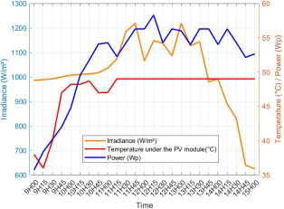
Figure 11. The monocrystalline PV/T module's cooling performance.
Figure 11 presents the performance of the final PV/T system with forced ventilation in operation. The results confirm the success of the cooling strategy. Effective Thermal Regulation: The forced airflow successfully counters the heat buildup. The module's temperature is actively regulated and capped at around 49°C during the most critical hours, thus preventing the overheating observed in the other two configurations.
Maximized and Sustained Electrical Output: Thanks to this temperature control, the electrical output is not only increased but, crucially, is sustained at a high level. The power reaches a value of 56.5 W and remains stable over a long period, unlike the reference module which suffered from degradation. The average daily power output of the optimized PV/T system rises to 51 W.
An unambiguous conclusion may be drawn from a direct comparison of the three configurations' average daily power outputs:
Table 3. Direct comparison of the average daily power outputs of the three configurations for monocrystalline panels.

Configuration

Peak Temperature

Average Power (9am-3pm)

Gain vs. Reference

Reference PV

51°C

45 W

-

Unventilated PV/T

58°C

44 W

-1 W (-2.2%)

Ventilated PV/T

49°C

51 W

+6 W (+13.3%)

Activating the forced-air cooling not only overcomes the detrimental effect of the casing but also generates a net power gain of 6 W, which represents a 13.3% improvement in electrical output compared to a standard module. This analysis experimentally validates the relevance and necessity of active cooling in the design of hybrid PV/T systems, transforming a potential thermal drawback into a significant performance advantage.
3.3.2. Analysis of Collector Performance with Polycrystalline PV Modules
The analysis is now conducted on the polycrystalline silicon module, subjected to the same three experimental configurations (reference, unventilated PV/T, and PV/T with cooling) and under the same solar irradiance conditions as before (average of 936.36 W/m2). The objective is to characterize its behavior and to quantify the effectiveness of cooling for this technology.
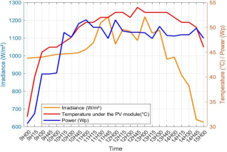
Figure 12. The standard polycrystalline PV module's performance.
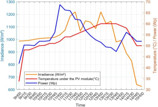
Figure 13. The polycrystalline PV/T module's performance without cooling.
Figure 12 presents the standard polycrystalline PV module's performance. The thermal behavior is similar to that of the monocrystalline module, although the temperatures reached are slightly higher. The rear surface temperature starts at 32°C and peaks at 54°C around 12:30 PM, with a daily average of 49.36°C. The polycrystalline module demonstrates a higher initial power output, reaching a peak of 61.5 W at 11:00 AM. However, it is also subject to thermal degradation, with its power dropping significantly in the afternoon to around 48 W. The daily average power for this reference module is 44 W.
Figure 13, which illustrates the unventilated polycrystalline PV/T case, confirms the previous observations. The confinement of air within the enclosure is just as detrimental for this technology. The rear surface temperature of the module reaches 58°C, a high value that severely inhibits performance. Although a power peak of 61.68 W is observed before the maximum overheating, the output then drops drastically to 48 W under the effect of the intense heat. The absence of active cooling negates any potential benefit of the system.
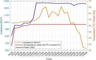
Figure 14. The polycrystalline PV/T module's cooling performance.
Figure 14 demonstrates the dramatic impact of active cooling on the polycrystalline module. The forced ventilation effectively regulates the temperature. After an initial rise, it is maintained at approximately 51°C during the hottest hours. Although this regulation temperature is slightly higher than for the monocrystalline (49°C), it remains significantly lower than the 58°C of the unventilated case. This thermal regulation allows the module to reach its full potential. The power climbs to 68.5 W and sustains this very high level, oscillating around this value until 3:00 PM. The optimized polycrystalline PV/T system's average daily power is 62.42 W.
The comparison of the three configurations for the polycrystalline module reveals an even more pronounced performance gain than for the monocrystalline module.
Table 4. Direct comparison of the average daily power outputs of the three configurations for polycrystalline panels.

Configuration (Polycrystalline)

Peak Temperature

Average Power (9am-3pm)

Gain vs. Reference

Reference PV

54°C

44 W

-

Unventilated PV/T

58°C

N/A

Negative

Ventilated PV/T

51°C

62.42 W

+18.42 W

In comparison to the reference polycrystalline module, active cooling improved electrical production by generating an additional average power of 18.42 W.
This result is particularly significant. It suggests that the polycrystalline module, although potentially more sensitive to heat (higher operating temperatures), benefits much more substantially from an active cooling system. The performance gain achieved is more than three times greater in absolute terms than that observed for the monocrystalline module (+18.42 W versus +6 W), positioning this technology as a potentially more attractive candidate for air-based PV/T applications.
3.3.3. Comparison of the Cooled Monocrystalline and Polycrystalline PV/T Modules' Electrical Power
A direct comparison of the two optimal PV/T systems—polycrystalline and monocrystalline—that use active cooling is the last step in this analysis. Figure 15 and Table 5 below summarize this direct comparison under identical solar irradiance conditions.
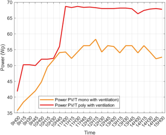
Figure 15. Power comparison of the cooled monocrystalline and polycrystalline PV/T modules.
Table 5. Performance Summary of the Cooled PV/T Systems.

Metric

Monocrystalline PV/T

Polycrystalline PV/T

Polycrystalline Advantage

Average Power

56 W

62,42 W

+6,42 W

Average Electrical Efficiency

14,57%

16,1%

+1,53 points

Average Thermal Efficiency

52%

56,46%

+14,46%

Optimal operating temperature

49°C

51°C

+2°C

The results reveal a clear and significant advantage for the collector with the polycrystalline solar module. It performs approximately 6.5 W better than the monocrystalline system (56 W) using an average energy consumption of 62.42 W. This superiority is also reflected in the average electrical efficiency, which is 1.53 percentage points higher for polycrystalline technology in this configuration.
This observation, although it may seem surprising given the generally higher nominal efficiency of monocrystalline cells under standard conditions (STC), corroborates the work of Toto et al. . Their research also indicated that polycrystalline modules may perform better at high operating temperatures, a condition that persists even with active cooling (control temperature of 51°C for polycrystalline versus 49°C for monocrystalline in our study). Our results suggest that this advantage of polycrystalline under hot conditions is not only confirmed but potentially amplified when integrated with this proposed collector.
It's also crucial to remember that the average electrical performances of our two optimized systems (14.57% and 16.1%) are better than the 13.67% value for a comparable air PV/T setup that Natalie et al reported .
The polycrystalline PV collector demonstrated higher thermal efficiency at 68.5%, compared to 59% for the monocrystalline PV collector, during the 10:00 a.m. to 2:00 p.m. period where solar irradiance varied from 980W/m2 to 1219W/m2. Under an average sunlight intensity of 1016 W/m2 (9:00 a.m. to 2:00 p.m.), the polycrystalline PV collector outperformed its counterpart. Its average thermal efficiency was measured at 56.46%, exceeding the 52% achieved by the monocrystalline PV collector. Heng Zhang et al.'s work on the effectiveness of flat-plate PV/T collectors with cooling channels yielded lower efficiencies than these (52.524%). This demonstrates the suggested PV/T air heat collector's effectiveness.
4. Conclusion
The primary problem of this effort was the deterioration of solar module performance brought on by high temperatures, a phenomena that is especially common in hot, sunny regions like southern Cameroon. The objective was twofold: firstly, to propose a new forced-air photovoltaic/thermal (PV/T) collector model to optimize electricity production; secondly, to conduct a rigorous experimental analysis to verify the efficiency of the collector using monocrystalline and polycrystalline silicon solar modules. In accordance with the methodology we used for the design, collection, and processing of data to obtain the results we presented and discussed, it appears that:
The proposed system has a collection surface area of 0.378 m2, which depends on the length and width of the solar module. It consists of a solar module with a peak power of 50Wp, a thermally insulated heat collector placed below the solar module at a height of 0.11 m from the air channel, and a 1.01W fan, which is not energy-intensive since the power gain obtained through optimization more than compensates for this. It allows heat to be removed from the collector to regulate the temperature below the PV modules. The pressure, P=11Pa, was taken into consideration while calculating the fan power, which also depends on the air channel: the larger the air channel, the greater the fan power, which is not recommended. The air flow in the collector varies according to the fan speed.
The suggested system was tested, and the data provided helped us optimize the production of photovoltaic solar modules. For both types of modules, active cooling significantly increased the power output. We quantified an average power gain of 9 W for the monocrystalline PV/T system (efficiency of 14.57%) and an even more substantial gain of 18 W for the polycrystalline PV/T system (efficiency of 16.1%) under average solar irradiation of 936.36 W/m2. With average efficiency rates of 52% for the collector with a monocrystalline solar module and 56.46% with a polycrystalline solar module, the system simultaneously showed that it could generate usable heat.
The major contribution of this work lies in the experimental demonstration that the proposed collector can maintain the temperature below the modules at 49°C for monocrystalline and 51°C for polycrystalline, which are the optimal operating temperatures for these types of modules in this area. Our results confirm the efficiency of the collector when the temperature is regulated by this proposed cooling system. When building air-based PV/T systems, especially in tropical locations, polycrystalline silicon modules may be a more rational optimization technique than monocrystalline modules.
Abbreviations

DC

Direct Curent

LCD

Liquid Crystal Display

PV

Photovoltaic

PV/T

Photovoltaic Thermal

RTC

Real-Time Clock

Conflicts of Interest
The authors declare no conflicts of interest.
References
[1] Saeed Abdul-Ganiyu, Investigation of Solar Photovoltaic-Thermal (PVT) and Solar Photovoltaic (PV) Performance: A Case Study in Ghana. Energies 2020, 13, 2701.
[2] N. Renewable Energy Lab, “NREL Best Research Cell Efficiencies Chart”, Accessed: Nov. 12, 2023.
[3] Sheik MS, Kakati P, Dandotiya D, CS R., “A comprehensive review on various cooling techniques to decrease an operating temperature of solar photovoltaic panels,” Energy Nexus, vol. 8, no. July, p. 100161, Dec. 2022,
[4] Abdulhammed K. Hamzat, Ahmet. Sahin, Mayowa I. Omisanya, Luai M. Alhems. Advances in PV and PVT cooling technologies: A review. Sustainable Energy Technologies and Assessments. Vol 47, October 2021, 101360.
[5] Hudișteanu S-V, Cherecheș N-C, Țurcanu F-E, Hudișteanu I, Verdeș M, Ancaș A-D. Experimental analysis of innovative perforated heat sinks for enhanced photovoltaic efficiency. Energy Convers Manage: X Jan. 2025; 25: 100842.
[6] TRIPANAGNOSTOPOULOS, MALEK A, HADDADI M, «Experimental study of the hybrid photovoltaic-thermal sensor, Renewable Energy Review 2007; 9: 143- 154.
[7] Tonui JK, TripanagnostopoulosY. Performance improvement of PV/T solar Collectors with natural air flow operation. Sol Energy 2008; 82(1): 1–12.
[8] Bilen, K.; Erdo ˘gan, I. Effects of Cooling on Performance of Photovoltaic/Thermal (PV/T) Solar Panels: A Comprehensive Review. Sol. Energy 2023, 262, 111829.
[9] Faraz Ahmad F, Said Z, Amine Hachicha A. Experimental performance evaluation of closed loop mist/fog cooling system for photovoltaic module application. Energy Convers Managem X May 2022; 14(March): 100226.
[10] Carmo, J. E., Torres, J. P. N., Cruz, G., & Marques Lameirinhas, R. A. Effect of the inclusion of photovoltaic solar panels in the autonomy of uav timeof flight. Energies, 2021, 14(4), 876.
[11] Zafar S, Fahad F A. Maximizing solar photovoltaic efficiency with Mist Cooled sandwich bifacial panels under extreme hot climate conditions. Energy Conversion and Management. May 2025;
[12] Niranjan Singh B, Nikhil Chander. Performance comparison of mono and polycrystalline silicon solar photovoltaic modules under tropical wet and dry climatic conditions in east-central India. Clean Energy, 2022, 6, 165–177.
[13] Ali HM. Recent advancements in PV cooling and efficiency enhancement integrating phase change materials based systems: a comprehensive review. Sol Energy, 2020, 197: 63–198.
[14] Fatih Bayrak, Hakan F. Oztop, Fatih Selimefendigil Experimental study for the application of different cooling techniques in photovoltaic (PV) panels Energy Convers Manag 2020.
[15] Nizetic S, Papadopoulos A M, Giama E. Comprehensive analysis and general economic-environmental evaluation of cooling techniques for photovoltaic panels, Part I: Passive cooling techniques. Energy Convers Manag 2017
[16] Harish K Khyani, Jayashri Vajpai, Rajendra Karwa. Experimental study of improved performance solar panels with cooling systems using fins and phase change materials on the rear plate. Journal of Solar Energy Engineering. 2025,
[17] Toto S, Ghazali O, Noreffendy T, Priyono S, Muhammad R-S, Angesta R & Mohamad Y. Performance comparison of monocrystalline and polycrystalline photovoltaic modules before testing with a cooling system. Cogent Engineering, 2024,
[18] Natalie AD, Pengfei L, Anas F, Yan Y, Vaclav D, Chuang W. Performance evaluation of a solar photovoltaic-thermal (PV/T) air collector system. Energy Conversion and Management: X 20 (2023) 100466.
[19] Malik F. Jaffar, Ahmed Qasim Ahmed, Abdulrahman Th. Mohammadand Wisam A M AlShohani. Performance evaluation of the polycrystalline photovoltaic module under Iraqi harsh weather conditions. International Journal of Advanced Technology and Engineering Exploration, 2022,
[20] Gong Y, Wang Z, Lai Z, Jiang M. TVACPSO-assisted analysis of the effects of temperature and irradiance on the PV module performances. Energy. 2021.
[21] Subhash Chander, A. Purohit, Anshu Sharma, Arvind, S. P. Nehra, M. S. Dhaka. A study on photovoltaic parameters of mono-crystalline silicon solar cell with cell temperature. Energy Reports.
[22] Basem, A.; Mukhtar, A.; Salem Elbarbary, Z. M.; Atamurotov, F.; Benti, N. E. Experimental study on the various varieties of photovoltaic panels (PVs) cooling systems to increase their electrical efficiency. PLoS ONE 2024, 19, e0307616.
[23] Grigore, R.; Vernica, S. G.; Popa, S. E.; Banu, I. V. Simulation and Experimental Results for Energy Production Using Hybrid Photovoltaic Thermal Technology. Energies 2024, 17, 1422.
[24] Hudis, teanu, V.-S.; Chereches,, N. C.; T, urcanu, F.-E.; Hudis, teanu, I.; Romila, C. Impact of Temperature on the Efficiency of Monocrystalline and Polycrystalline Photovoltaic Panels: A Comprehensive Experimental Analysis for Sustainable Energy. Sustainability 2024; 16: 10566.
[25] Mohammad E. Kashan, AlanS.Fung, Amir Hossein Eisapour, John Swift. Utilizing novel industrialized heat exchanger plate in air-based photovoltaic/thermal collectors to enhance thermal and electrical efficiency. Energy Convers Manag X 2024; 24: 00752.
[26] Chandrasekar M, Suresh S, Senthilkumar T, Ganeshkarthikeyan M. Passive cooling of standalone flat PV module with cotton wick structures. Energy Convers Manag 2013; 71(JournalArticle): 43–50.
[27] Jin-Hee Kim, Se-Hyeon Park, Jun-Tae Kim. Experimental performance of a photovoltaic-thermal air collector. Energy Procedia 2014; 48: 888–94.
[28] Si chaib, A., Khaled, A. & Sari, Z. H. Etude d’un système de captation-stockage de l’énergie solaire thermique. International Journal of Scientific Research & Engineering Technology (IJSET), 2014; 3: 60–65.
[29] Heng zhang, Liu Haowen, Chen Haiping, Guo Xinxine, Liang Kai, Yao Pengbo. Research on the Performance of Flat-Box Photovoltaic/Thermal Collector with Cooling Channels. Journal of Solar Energy Engineering, 2018,
Cite This Article
  • APA Style

    Alexis, L. K., Stephane, K. L., Pierre, P. M. J., Fabrice, M. K., Kewir, T. J. (2026). Development and Experimental Evaluation of a New Photovoltaic-thermal Air Collector to Optimise the Performance of PV Solar Modules. International Journal of Sustainable and Green Energy, 15(1), 31-44. https://doi.org/10.11648/j.ijsge.20261501.14

    Copy | Download

    ACS Style

    Alexis, L. K.; Stephane, K. L.; Pierre, P. M. J.; Fabrice, M. K.; Kewir, T. J. Development and Experimental Evaluation of a New Photovoltaic-thermal Air Collector to Optimise the Performance of PV Solar Modules. Int. J. Sustain. Green Energy 2026, 15(1), 31-44. doi: 10.11648/j.ijsge.20261501.14

    Copy | Download

    AMA Style

    Alexis LK, Stephane KL, Pierre PMJ, Fabrice MK, Kewir TJ. Development and Experimental Evaluation of a New Photovoltaic-thermal Air Collector to Optimise the Performance of PV Solar Modules. Int J Sustain Green Energy. 2026;15(1):31-44. doi: 10.11648/j.ijsge.20261501.14

    Copy | Download

  • @article{10.11648/j.ijsge.20261501.14,
      author = {Lontsi Kuefouet Alexis and Kenfack Lontsi Stephane and Pesdjock Mathieu Jean Pierre and Mbakop Kwefeu Fabrice and Tangka Julius Kewir},
      title = {Development and Experimental Evaluation of a New Photovoltaic-thermal Air Collector to Optimise the Performance of PV Solar Modules},
      journal = {International Journal of Sustainable and Green Energy},
      volume = {15},
      number = {1},
      pages = {31-44},
      doi = {10.11648/j.ijsge.20261501.14},
      url = {https://doi.org/10.11648/j.ijsge.20261501.14},
      eprint = {https://article.sciencepublishinggroup.com/pdf/10.11648.j.ijsge.20261501.14},
      abstract = {One of the main challenges to the performance of photovoltaic (PV) modules is the reduction in efficiency resulting from their high working temperature. Air-based photovoltaic/thermal (PV/T) devices offer a solution. This work presents the development of a photovoltaic/thermal air heat collector to optimize the performance of PV modules: Experimental case with monocrystalline and polycrystalline silicon photovoltaic solar modules. This was accomplished by designing, constructing, and positioning a thermal collector under the solar modules that had a surface area of 0.378 m2 and a height of 0.11 m. A real-time experimental study conducted on a sunny day in the courtyard of ISABEE of university of Ebolowa, Cameroon, showed that the proposed collector maintained the temperature below the monocrystalline solar panel at 49°C and that of the polycrystalline panel at 51°C, respectively, in order to an average power of 56.24 W (a power gain of 9 W compared to conventional PV) for the monocrystalline panel and 62.4 W (a power gain of 18 W) for the polycrystalline panel. DC fans where set up at the collector’s outlet were used to control the air flow rate to optimize cooling. In terms of thermal performance, a power output of 242 W (52% efficiency) was achieved for the monocrystalline module, while the polycrystalline module reached 295.94 W (56.46% efficiency). The tests, conducted under average sunlight of 936.36 W/m2 (between nine in the morning and three in the afternoon), demonstrated the system's efficiency. This study not only validates the optimization of electrical and thermal performance using the proposed technique, but also reveals the different behavior of the two types of cells. This collector can be considered highly suitable for optimizing the efficiency of PV modules in domestic solar installations, particularly in regions with an equatorial climate (such as the southern region of Cameroon) and high ambient temperatures.},
     year = {2026}
    }
    

    Copy | Download

  • TY  - JOUR
    T1  - Development and Experimental Evaluation of a New Photovoltaic-thermal Air Collector to Optimise the Performance of PV Solar Modules
    AU  - Lontsi Kuefouet Alexis
    AU  - Kenfack Lontsi Stephane
    AU  - Pesdjock Mathieu Jean Pierre
    AU  - Mbakop Kwefeu Fabrice
    AU  - Tangka Julius Kewir
    Y1  - 2026/02/06
    PY  - 2026
    N1  - https://doi.org/10.11648/j.ijsge.20261501.14
    DO  - 10.11648/j.ijsge.20261501.14
    T2  - International Journal of Sustainable and Green Energy
    JF  - International Journal of Sustainable and Green Energy
    JO  - International Journal of Sustainable and Green Energy
    SP  - 31
    EP  - 44
    PB  - Science Publishing Group
    SN  - 2575-1549
    UR  - https://doi.org/10.11648/j.ijsge.20261501.14
    AB  - One of the main challenges to the performance of photovoltaic (PV) modules is the reduction in efficiency resulting from their high working temperature. Air-based photovoltaic/thermal (PV/T) devices offer a solution. This work presents the development of a photovoltaic/thermal air heat collector to optimize the performance of PV modules: Experimental case with monocrystalline and polycrystalline silicon photovoltaic solar modules. This was accomplished by designing, constructing, and positioning a thermal collector under the solar modules that had a surface area of 0.378 m2 and a height of 0.11 m. A real-time experimental study conducted on a sunny day in the courtyard of ISABEE of university of Ebolowa, Cameroon, showed that the proposed collector maintained the temperature below the monocrystalline solar panel at 49°C and that of the polycrystalline panel at 51°C, respectively, in order to an average power of 56.24 W (a power gain of 9 W compared to conventional PV) for the monocrystalline panel and 62.4 W (a power gain of 18 W) for the polycrystalline panel. DC fans where set up at the collector’s outlet were used to control the air flow rate to optimize cooling. In terms of thermal performance, a power output of 242 W (52% efficiency) was achieved for the monocrystalline module, while the polycrystalline module reached 295.94 W (56.46% efficiency). The tests, conducted under average sunlight of 936.36 W/m2 (between nine in the morning and three in the afternoon), demonstrated the system's efficiency. This study not only validates the optimization of electrical and thermal performance using the proposed technique, but also reveals the different behavior of the two types of cells. This collector can be considered highly suitable for optimizing the efficiency of PV modules in domestic solar installations, particularly in regions with an equatorial climate (such as the southern region of Cameroon) and high ambient temperatures.
    VL  - 15
    IS  - 1
    ER  - 

    Copy | Download

Author Information
  • Department of Rural Engineering, University of Ebolowa, Ebolowa, Cameroon

  • Department of Rural Engineering, University of Ebolowa, Ebolowa, Cameroon

  • Department of Rural Engineering, University of Ebolowa, Ebolowa, Cameroon

  • Department of Rural Engineering, University of Ebolowa, Ebolowa, Cameroon

  • Department of Rural Engineering, University of Ebolowa, Ebolowa, Cameroon

  • Abstract
  • Keywords
  • Document Sections

    1. 1. Introduction
    2. 2. Materials and Methods
    3. 3. Results and Discussions
    4. 4. Conclusion
    Show Full Outline
  • Abbreviations
  • Conflicts of Interest
  • References
  • Cite This Article
  • Author Information