Abstract
With the rapid growth of deep foundation‑pit engineering, construction‑related risks have become increasingly prominent. Traditional automatic monitoring approaches are difficult to satisfy the demands of wireless transmission and real‑time risk warning, which restricts the risk‑management performance of foundation‑pit projects. To address this limitation, this paper proposes an Internet‑of‑Things (IoT)‑enabled wireless monitoring technique for deep foundation pits, aiming to achieve continuous wireless data perception and intelligent risk early‑warning for excavation engineering. Taking an actual deep foundation‑pit project in Shanghai as the research object, multi‑parameter automatic monitoring, including inclinometer deformation, groundwater level and static leveling settlement, is implemented by the developed IoT monitoring system. Field comparisons against manual observation data verify that the proposed technique can satisfy engineering data‑accuracy specifications. Moreover, it effectively reduces early‑warning response latency and cuts the expenditure on cable‑laying work. This work validates the practicability of low‑power IoT solutions and indicates promising application potential of such technologies in geotechnical monitoring domains.
Keywords
Internet of Things, Deep Foundation Pit, Wireless Monitoring
1. Introduction
With the accelerated urbanization process, super high-rise buildings and deep foundation pit projects in densely populated areas are growing rapidly. The foundation pit monitoring system serves not only as a vital measure to guarantee the construction safety of foundation pits, but also as a "smart eye" for safeguarding underground space safety. Driven by innovative IoT sensing technologies, modern foundation pit monitoring is transforming from discrete manual monitoring to full-range digital real-time monitoring. The exponential development of IoT technology has profoundly reshaped the technical ecosystem of deep foundation pit monitoring, pushing this field into a new stage featuring integrated multi-disciplinary technologies.
At present, traditional monitoring transmission technologies require simultaneous layout of various cables including power lines, signal lines and control lines, together with supporting power supply accessories such as security power supplies, sockets and PVC (Polyvinyl Chloride) conduits. This inevitably results in redundant and crossed cables on site, accompanied by time-consuming and labor-intensive construction. The construction environment of deep foundation pits is relatively complicated, bringing great difficulties to on-site cable protection. Cable damage at a single node caused by construction activities may easily paralyze the signal of the entire branch. This paper applies IoT wireless monitoring technology to deep foundation pit monitoring, which eliminates a large number of cables and accessories, cuts corresponding construction working hours and reduces the difficulty of on-site cable protection.
In recent years, numerous studies have focused on the integrated application of Internet of Things (IoT) technology in complex deep foundation pit monitoring scenarios. Deng et al.
| [1] | Deng N D, Lai G H, Lu M, et al. Research on deep foundation pit monitoring method of smart construction site based on Internet of Things technology [J]. Sichuan Building Materials, 2023, 49(11): 94-96, 99. |
[1]
proposed a design scheme of intelligent monitoring systems for deep foundation pits based on IoT architecture, which adopted the RS485 bus to connect sensors and host equipment for stable transmission of monitoring data. Cai and Liu
developed a deep foundation pit dewatering control system relying on ZigBee wireless communication technology, which realized intelligent regulation of underground water level during foundation construction. Chen et al.
| [3] | Chen Q R, Yang C, Zhu D F, et al. Research and application of deep foundation pit monitoring method based on Cat. 1 technology and array displacement meters [J]. Guangdong Civil Engineering & Architecture, 2024, 31(03): 1-5.
https://doi.org/10.19731/j.gdtmyjz.2024.03.001 |
[3]
established a wireless automatic monitoring method combining Cat. 1 communication technology and array displacement sensors, which effectively realized deformation monitoring and early warning for deep foundation pit construction. Wang et al.
| [4] | Wang J Y, Wu S, Yao L B, et al. Function and architecture design of IoT perception platform for infrastructure construction site [J]. Scientific and Technological Innovation, 2021(01): 71-72. |
[4]
constructed an on-site IoT perception platform for infrastructure engineering, which adopted intelligent bracelets and mobile intelligent terminals to complete multi-source data collection in electric power construction sites. Yang et al.
| [5] | Yang S J, Wang J F, Yang M, et al. Research on intelligent monitoring technology applied in top-down construction of super-large deep foundation pits [J]. Construction Technology, 2024, 53(11): 121-125. |
[5]
applied NB-IoT sensing technology to dynamically and real-timely acquire monitoring data from key measuring points in deep foundation pit engineering. Tan D et al.
| [6] | Tan, D., Li, A., Ji, B., Duan, J., Tao, Y., Luo, H. Ground Deformation Monitoring for Subway Structure Safety Based on GNSS. Buildings. 2023, 13, 2682.
https://doi.org/10.3390 /buildings 13112682 |
[6]
established a GNSS (Global Navigation Satellite System) monitoring system with the RLMD-SVD (Robust Local Mean Decomposition- Singular Value Decomposition) denoising method for automated and high-precision subway deformation monitoring. Wei Z et al.
| [7] | Wei, Z., Sun, C., Yang, G., Wang, H., Yang, G. Automated Monitoring of Deep Excavations Using Fiber Bragg Grating Technology. Frontiers in Earth Science. 2026, 14, 1766390.
https://doi.org/10.3389/feart.2026.1766390 |
[7]
developed an FBG (Fiber Bragg Grating)-based automatic monitoring system for foundation pits to overcome the defects of traditional monitoring technologies. Fan H et al.
| [8] | Fan, H., Li, L., Zhou, S., Zhu, M., Wang, M. Prediction and Risk Assessment of Lateral Collapse in Deep Foundation Pits Using Machine Learning. Automation in Construction. 2025, 171, 106011. https://doi.org/10.1016/j.autcon.2025.106011 |
[8]
proposed an optimized LSTM (Long‑Short‑Term Memory) prediction method based on machine learning to predict foundation pit lateral deformation and identify high-risk areas. Zhang R et al.
| [9] | Zhang, R., Chang, H., Goh, A. T. C. Review of Recent Developments in AI‑based Data Processing and Prediction for Braced Excavation Design. Intelligent Transportation Infrastructure. 2024, 3, liae014. https://doi.org/10.1093/iti/liae014 |
[9]
reviewed AI applications in braced excavation monitoring and prospected future generative AI research directions. Xu Y et al.
| [10] | Xu, Y., Dai, X., Zhang, H., Ma, Z. Deformation Monitoring and Analysis of Deep Foundation Pit Construction Period Based on Internet of Things Technology. Scalable Computing: Practice and Experience. 2025, 26(2), 766‑774.
https://doi.org/10.1269 4/scpe.v26i2.4075 |
[10]
adopted an IoT and neural network-based method for high-precision deformation prediction of deep foundation pits. Li H et al.
constructed an edge-cloud collaborative intelligent monitoring system to realize rapid early warning and closed-loop risk management of foundation pits.
2. Low-Power Wireless Networking Monitoring Technology for Deep Foundation Pits
Wireless Ad Hoc Network refers to a distributed wireless communication technology independent of fixed infrastructures such as base stations and routers. Nodes in the network (including sensors, terminal devices, gateways, etc.) establish connections through autonomous negotiation, dynamic networking and multi-hop relay. Characterized by decentralization and self-adaptability, the technology improves the flexibility and anti-destruction performance of communication networks
.
The monitoring environment of deep foundation pits is relatively complicated. On the one hand, concrete and steel bars inside the pit will block wireless signals; on the other hand, power supply conditions at construction sites are limited. Accordingly, the communication technology is required to feature strong penetration, long-distance transmission and ultra-low power consumption. As shown in
Table 1, commonly used WiFi (Wireless‑Fidelity) and Bluetooth technologies fail to meet the on-site communication demands. ZigBee suffers from short communication distance and weak penetration, making it hard to achieve full coverage of deep foundation pits. NB-IoT relies on cellular base stations, and signal coverage may be unavailable inside foundation pits; it also has relatively high power consumption and requires operator service fees. In contrast, LoRa possesses outstanding advantages including strong penetration within the Sub-1GHz frequency band, long-distance transmission, anti-interference capability via independent networking and ultra-low power consumption, which make it well-suited for the complex environment of deep foundation pits with low long-term operation and maintenance costs. Therefore, LoRa serves as the optimal communication option for this scenario
| [13] | Liang Y R, Gao J, Yan L. Research on urban underground space transmission system based on ZigBee Mesh network and NB-IoT [J]. Water Resources and Hydropower Engineering, 2022, 3(08): 71-77.
https://doi.org/10.13928/j.cnki.wrahe.2022.08.00 7 |
[13]
.
Table 1. ZigBee, LoRa, NB-IoT related parameters comparison table.
Technical Indicators | Zigbee | LoRa | NB-IoT |
Networking Architecture | Mesh network Supports multi-hop self-organizing networking | Star or hybrid networking topology Supports private network deployment | Cellular star networking, relies on operator base stations |
Communication Distance | Short distance (10–100 m) | Long transmission distance (1–10 km) | Wide coverage (Reliant on cellular base stations) |
Power Consumption Characteristics | Extremely low (Battery life ranges from several months to several years) | Ultra-low power consumption (Battery life of several years) | Moderate power consumption (Requires regular charging or battery replacement) |
Transmission Rate | 20-250 kbps | 0.3-50 kbps | 20-200 kbps |
Network Capacity | Supports up to 65,000 nodes | Millions of nodes (Dedicated gateways required) | A single base station supports ten-thousand-level connections |
Security Performance | AES-128 encryption | AES-128 encryption | Operator-grade SIM card authentication |
Frequency Band and Cost | 2.4 GHz (License-free frequency band with low cost) | Sub-1GHz (License-free frequency band, low cost) | Licensed frequency band (requires operator support, relatively high cost) |
LoRa (Long Range Radio) is a Low Power Wide Area Network (LPWAN) technology specially designed for IoT applications. LoRa transmits data via linear chirp signals whose frequency varies linearly over time. This modulation technique delivers strong anti-interference capability and is robust against multipath fading and Doppler effects
| [14] | Maleki A, Nguyen H H, Bedeer E, et al. A tutorial on chirp spread spectrum for LoRaWAN: Basics and key advances [J]. arXiv preprint arXiv: 2310.10503(2023). |
[14]
.
LoRaWAN (Long‑Range Wide‑Area Network) performance degrades relatively under ultra-long-distance transmission or complex environments due to path loss. Generally speaking, path loss is proportional to the square of distance in free space. Nevertheless, in harsh scenarios such as urban deep trenches and underground mines, signal propagation is further blocked by terrain and obstacles, and path loss follows the log-distance model
| [15] | Rademacher M, Linka H, Horstmann T, et al. Path loss in urban LoRa networks: A large-scale measurement study [C] // 2021 IEEE 94th Vehicular Technology Conference (VTC2021-Fall), IEEE: 1-6(2021). |
[15]
.
(1)
Wherein, Lp denotes path loss, L0 represents path loss at the reference distance, d0 is the reference distance, d stands for transmission distance, and n refers to the path loss exponent. In addition, dense metal structures in deep foundation pits will increase signal penetration loss and further attenuate signal strength. To tackle the aforementioned challenges, a LoRa Relay Network (LRN) architecture and a Beacon-Coordinated Dynamic Time Division Access (BCD-TDA) scheme are proposed to mitigate uplink collisions among end nodes.
2.1. Introduction to LoRa-Based Wireless Ad Hoc Network Technology
A frequency division mechanism is designed to address the collision avoidance requirements arising from dense deployment of multiple nodes inside complex deep foundation pits. The available frequency band is divided into several fixed channels according to the available bandwidth, forming independent frequency bands free of mutual interference. Within each fixed frequency band, a time division mechanism for collision avoidance is implemented to reduce the probability of collisions under high-concurrency conditions. The combination of time and frequency mechanisms ultimately forms a time-frequency multiplexing-based collision timeslot management scheme. Furthermore, a node sleep and over-the-air wake-up function is developed based on active signal detection technology, enabling bidirectional low-power wireless communication between gateways and nodes under star and relay hybrid networking modes.
The communication process of the LoRa Relay Network (LRN) architecture consists of two segments: gateway-to-relay nodes and relay-node-to-end nodes. The gateway can receive messages over eight channels simultaneously. Each channel is allocated to either one relay device within the relay network, or seven end nodes in the star network for uplink communication with the gateway.
End nodes realize energy conservation by alternating between wake-up listening and sleep cycle modes. The communication module stays in receive mode by default and periodically wakes up to monitor downlink relay wake-up notifications and uplink relay wake-up notifications transmitted by relay devices. Based on the low-power control timeline of the network, the entire networking protocol is divided into three parts: the communication protocol for intelligent gateways, the communication protocol for relay devices, and the communication protocol for end nodes.
2.2. Research and Development of Low-Power Wireless Acquisition Hardware
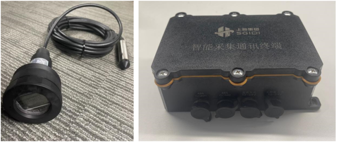
The digital signal acquisition terminal is mainly applied to wireless data collection and transmission of digital-output sensors in foundation pit engineering. Sensors adopted for monitoring items such as water level, settlement and inclinometry generally adopt digital signal output formats. Integrated with ultra-low-power STM32L4 series microcontrollers and LoRa modules, the terminal realizes wireless collection and transmission of data from digital sensors. To meet the engineering requirements of wireless deployment, two product versions including single-channel and dual-channel types are designed.
The single-channel digital signal acquisition terminal is mainly designed for groundwater level monitoring. This integrated acquisition and transmission device can be installed inside water level boreholes to realize wireless data collection and transmission, and it is adopted for data acquisition at discrete monitoring points in foundation pit sites. In contrast, the dual-channel digital signal acquisition terminal is suitable for monitoring points with multiple sensors connected in series via a single interface, such as inclinometer and settlement sensors.
Figure 1. Digital signal intelligent acquisition terminal physical photos (left: single channel, right: dual channel).
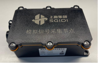
The analog signal acquisition terminal is mainly used for data collection of vibrating wire sensors such as rebar meters, strain gauges, earth pressure cells and pore water pressure transducers in foundation pit engineering. Such sensors commonly suffer from discrete monitoring points and small quantities per group in foundation pit projects. In particular, monitoring for strut axial force generally requires four sensors to form one measuring point. Therefore, in combination with practical engineering requirements, the terminal takes the STM32L431RCT6 microcontroller as the core. Each functional module is controlled through native pins of the STM32 chip to realize multi-channel vibrating wire signal acquisition, GPS positioning, battery voltage detection and other functions.
Figure 2. The physical photo of the analog signal intelligent acquisition terminal.
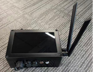
LoRa nodes cannot directly communicate and interact with the cloud, so a LoRa gateway is required on site. Bidirectional communication between gateways and nodes is realized via the wireless ad hoc network protocol, and data exchange with the cloud system is completed through the built-in 4G communication module of the LoRa gateway. Accordingly, a four-layer PCB (Printed Circuit Board) layout is adopted with reasonable layout of all RF chips to integrate subsystems including Linux main control board, LoRa transceiver, 4G communication, GNSS positioning, power management and RS485 communication. A waterproof enclosure is also designed and fabricated to realize integrated management of control boards, power supplies, antennas and other modules.
Figure 3. The multifunctional integrated intelligent gateway physical photo.
2.3. Development of Automatic Monitoring System Based on Internet of Things
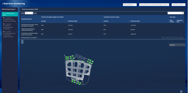
The IoT automatic monitoring system is an efficient data processing and analysis platform built with a microservice architecture and developed via the front-end and back-end separation pattern. The microservice architecture decomposes complex business logic into multiple independent and autonomous services, each undertaking a specific set of functions, which improves the maintainability and scalability of the system. The separated front-end and back-end development model enables front-end and back-end developers to carry out development in parallel, greatly boosting development efficiency and system response speed. The overall system design fully takes future business expansion requirements into account to guarantee system stability and reliability, and delivers efficient and convenient data processing and analysis services for users. Adopting a layered architecture and modular design, the system realizes functional modules including equipment entry, equipment-measuring point binding, data acquisition, real-time control, data visualization, and data analysis and processing.
Figure 4. The comprehensive evaluation form of project automatic monitoring data.
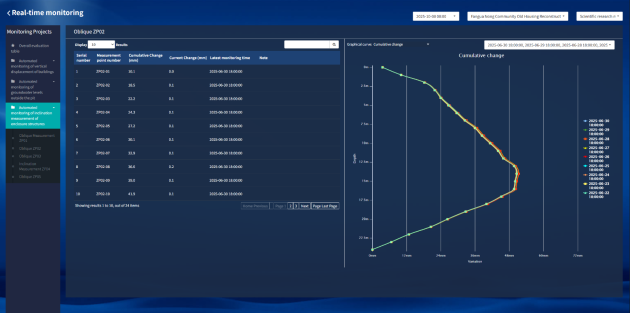
Figure 5. The automatic inclinometer monitoring data interface.
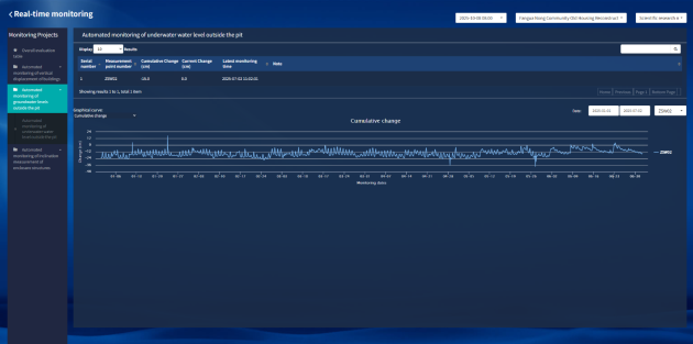
Figure 6. The automatic water level monitoring data interface.
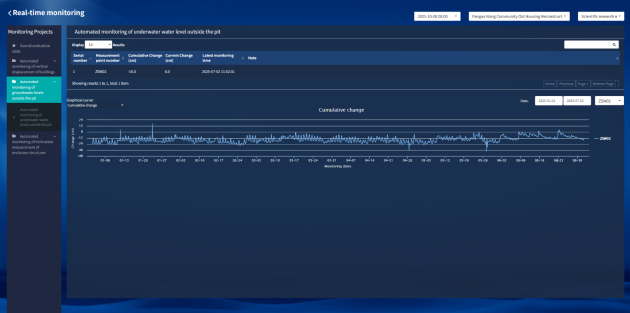
Figure 7. The automatic hydrostatic leveling monitoring data interface.
3. Field Application
3.1. Project Overview
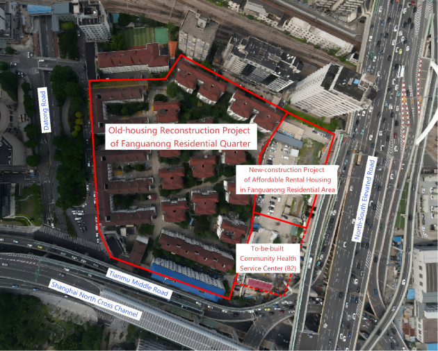
A deep foundation pit project in Jing'an District, Shanghai, is bounded by North Tianmu West Road to the north, East Datong Road to the east and West Gonghexin Road to the west. The main buildings consist of five reconstruction projects of old residential buildings and one new construction project of indemnificatory rental housing. Two underground floors are arranged across the whole site; a partial single underground floor is located on the south side of the reconstruction area. The foundation adopts pile-raft foundation. The excavation area of the first basement floor is 900 m², and that of the second basement floor is 22000 m², with the maximum excavation depth of the foundation pit reaching 10.3 m.
In terms of surrounding environments, the closest distance from the east excavation boundary of the pit to the land red line is approximately 4.6 m, adjacent to Gonghexin Road (North-South Elevated Road and auxiliary roads) and a planned plot (to-be-built community health service center). The minimum distance from the south excavation boundary to the land red line ranges from 14.7 m to 28.9 m, next to Tianmu Middle Road, with a police station retaining natural shallow foundation within the red line. The shortest distance from the west excavation boundary to the land red line is about 4.6 m, and Datong Road is closely attached outside the red line. The closest distance from the north excavation boundary to the land red line is roughly 5.9 m, bordering a school with natural shallow foundation, residential buildings and office buildings.
Various underground pipelines including gas, water supply, sewage, power supply, communication and telecommunication pipelines with shallow burial depth and short distance to the foundation pit are distributed around the site.
Numerous pipelines and complex buildings are distributed around the foundation pit of this project. The project features multiple construction procedures, long construction period, complex construction techniques and heavy workload, imposing strict requirements on the protection of surrounding environment and the foundation pit itself. Real-time monitoring of soil displacement around the pit, confined water outside the pit and stress variations is required to guarantee that foundation pit deformation stays within allowable limits, so as to mitigate adverse impacts on pipelines, roads, surrounding important buildings and municipal facilities. During the excavation of the foundation pit, wireless ad hoc network technology is adopted to carry out real-time automatic monitoring of key measurement items including deep horizontal displacement of retaining structures, hydrostatic leveling and underground water level.
Figure 8. The schematic diagram of the surrounding environment of a deep foundation pit project in Shanghai.
3.2. Application Status
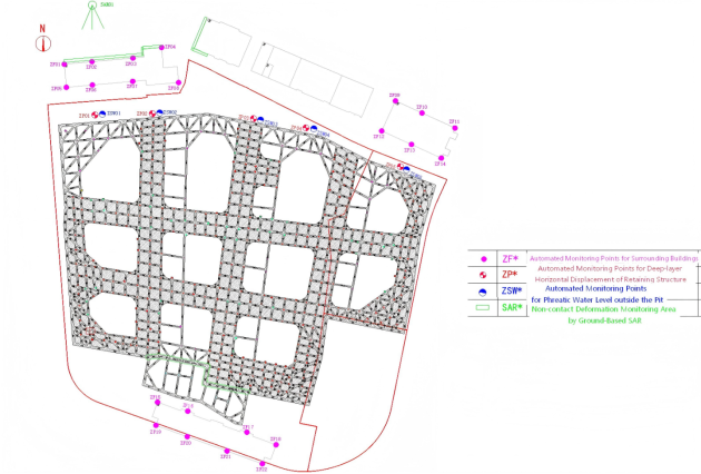
The automatic monitoring of key measurement items such as deep horizontal displacement, hydrostatic leveling and underground water level of the foundation pit is realized based on low-power wireless networking monitoring technology. The application scheme of automatic accurate sensing technology is shown in
Table 2. A total of 5 sets of automatic distributed inclinometers, 22 sets of automatic hydrostatic leveling instruments and 5 sets of automatic wireless water level monitors are deployed on site. One set of gateway can complete the collection of all data from wireless acquisition terminals. The collected data is preprocessed at the edge end and then synchronized to the cloud-based automatic monitoring system for data processing and analysis.
Figure 9. The layout of automatic monitoring points for a deep foundation pit project in shanghai.
Table 2. The application scheme of automatic precision sensing technology.
monitoring contents | monitoring methods | quantity | depth | position |
deep horizontal displacement of retaining structure (inclinometry) | distributed inclinometry | 5 boreholes | 26m | north side of foundation pit |
phreatic water level outside the pit | wireless water level monitoring | 5 boreholes | 8m | Same positions as inclinometer holes |
vertical displacement of buildings | hydrostatic leveling | 22 measuring points (3 buildings) | - | 8 m depth; 6–8 measuring points per building, with one point arranged at each building corner and midpoint of long sides |
3.3. Automated Monitoring of Deep Horizontal Displacement of the Retaining Structure
This project focuses on the research, development and application of distributed MEMS (Micro‑Electro‑Mechanical System) automatic inclinometry technology. By innovatively developing retractable adaptive components, modular assembly and efficient recycling of MEMS automatic inclinometers are achieved, which significantly improves equipment performance.
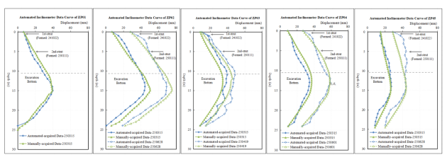
In line with the progress of on-site construction, 5 sets of automatic inclinometers with a depth of 24 m are installed on the north side of the foundation pit for automatic monitoring of deep horizontal displacement, so as to capture the real-time dynamic deformation of the retaining structure. Comparative verification with manual repeated measurements at adjacent positions indicates that the maximum deviation is about 6 mm.
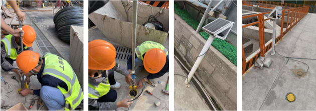
Figure 10 shows the on-site installation diagram of the automatic inclinometers adopted in this project;
Figure 11 presents the comparison curve of automatic inclinometry data and manual measurement data;
Table 3 summarizes the comparative analysis of automatic and manual inclinometry data.
Figure 10. On-site installation diagram of automatic inclinometer equipment.
Table 3. The comparative analysis table of inclination automation data and manual data.
automatic monitoring data | manual measurement data | deviation |
point number | Variation (mm) | point number | Variation (mm) | variation difference (mm) |
ZP01 | 39.8 | CX06 | 39.5 | -0.3 |
ZP02 | 69.2 | CX07 | 75.28 | 6.08 |
ZP03 | 48.6 | CX10 | 45.5 | -3.1 |
ZP04 | 58.9 | CX11 | 58.58 | -0.32 |
ZP05 | 45.2 | CX13 | 44.16 | -1.04 |
Figure 11. The inclination automatic data and manual data comparison curve.
3.4. Automated Monitoring of Groundwater Level outside the Foundation Pit
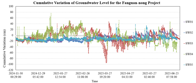
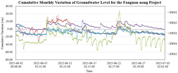
Five groups of automatic water level monitoring points are arranged on the north side of the foundation pit for automatic monitoring of the phreatic water level outside the pit. The monitoring data demonstrate that the groundwater level remains relatively stable, with fluctuations mainly induced by rainfall.
As shown in
Figure 12, the maximum cumulative variation of water level in this project is less than 100 cm. As illustrated in
Figure 13, the maximum cumulative water level variation within one month (June 2025 – July 2025) is less than 60 cm.
Figure 12. The cumulative variation curve of water level.
Figure 13. The cumulative change curve of water level with a period of one month.
3.5. Automated Monitoring of Sensitive Buildings Using Static Leveling
Hydrostatic leveling monitoring points are installed at the corners of three buildings A, B and C, with a total of 22 measuring points. The monitoring points on the side far away from the foundation pit are taken as reference benchmarks to carry out automatic monitoring of differential settlement, and the time-history deformation curves of surrounding buildings are accurately captured.
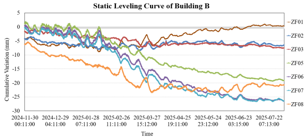
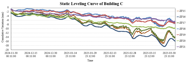
Since the deformation data of Building A remains relatively stable, the corresponding manual measurement data of Building B and Building C within the same monitoring period are selected for comparative analysis. The trends of automatic monitoring data and manual measurement data are basically consistent, with an average deviation of approximately 3 mm.
1) Building B monitoring period: 30 November 2024 – 04 August 2025, maximum deviation: 8.22 mm, average deviation: 3.9 mm
2) Building C monitoring period: 30 November 2024 – 04 April 2025, maximum deviation: 6.8 mm, average deviation: 2.6 mm
As illustrated in the figures:
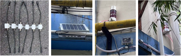
Figure 14 shows the schematic diagram of hydrostatic leveling sensors and their on-site installation;
Figure 15 presents the hydrostatic leveling curve of Building B;
Figure 16 shows the hydrostatic leveling curve of Building C;
Table 4 summarizes the comparative analysis of automatic monitoring data and manual measurement data for Building B;
Table 5 lists the comparative analysis of automatic monitoring data and manual measurement data for Building C.
Table 4. The comparative analysis table of static level automatic data and manual data of B-building house.
automatic monitoring data | manual measurement data | deviation |
point number | Variation (mm) | point number | Variation (mm) | variation difference (mm) |
ZF01 | -5.62 | F19 | -3.2 | 2.42 |
ZF02 | -12.69 | F20 | -8.5 | 4.19 |
ZF03 | -13.58 | F21 | -9.5 | 4.08 |
ZF04 | -5.9 | F23 | -5.9 | 0 |
ZF05 | -25.11 | F29 | -16.9 | 8.21 |
ZF06 | -32.32 | F28 | -24.1 | 8.22 |
ZF07 | -32.35 | F26 | -28 | 4.35 |
ZF08 | -26.79 | F25 | -26.3 | 0.49 |
Figure 14. The static level sensor and field installation diagram.
Table 5. The comparative analysis table of static level automatic data and manual data of C-building house.
automatic monitoring data | manual measurement data | deviation |
point number | Variation (mm) | point number | Variation (mm) | variation difference (mm) |
ZF15 | -15.34 | F1 | -10.9 | 4.44 |
ZF16 | -17.03 | F2 | -13.3 | 3.73 |
ZF17 | -15.33 | F4 | -8.5 | 6.83 |
ZF18 | -8.56 | F5 | -5.6 | 2.96 |
ZF19 | -8.57 | F10 | -12.3 | -3.73 |
ZF20 | -11.05 | F9 | -7.8 | 3.25 |
ZF21 | -7.95 | F7 | -4.1 | 3.85 |
ZF22 | -1.1 | F6 | -1.1 | 0 |
Figure 15. The hydrostatic level curve of the B-house.
Figure 16. The hydrostatic level curve of the C-house.
4. Conclusion
The research and development of the IoT-based wireless networking monitoring technology for complex deep foundation pits effectively realizes the wireless collection of multi-item and multi-source discrete sensor data, including inclinometry, water level, and axial force in deep foundation pit monitoring scenarios. Relying on LoRa gateways, all local monitoring data are aggregated and synchronously transmitted to the real-time monitoring system. The application of wireless transmission technology addresses the inherent drawbacks of traditional wired monitoring systems, such as complicated wiring, data lag, and poor anti-interference capability. Verified by practical engineering cases, the proposed technology supports minute-level real-time monitoring of massive automated monitoring data. Furthermore, the automatic early warning function of the IoT platform significantly shortens the early warning response time. Meanwhile, the wireless networking technology substantially reduces cable costs compared with conventional wired connection methods.
Abbreviations
IoT | Internet‑of‑Things |
PVC | Polyvinyl Chloride |
NB-IoT | Narrowband Internet of Things |
GNSS | Global Navigation Satellite System |
RLMD | Robust Local Mean Decomposition |
SVD | Singular Value Decomposition |
FBG | Fiber Bragg Grating |
LSTM | Long‑Short‑Term Memory |
WiFi | Wireless‑Fidelity |
LoRa | Long Range Radio |
LPWAN | Low Power Wide Area Network |
LoRaWAN | Long‑Range Wide‑Area Network |
LRN | LoRa Relay Network |
BCD-TDA | Beacon-Coordinated Dynamic Time Division Access |
PCB | Printed Circuit Board |
MEMS | Micro‑Electro‑Mechanical System |
Conflicts of Interest
The authors declare no conflicts of interest.
References
| [1] |
Deng N D, Lai G H, Lu M, et al. Research on deep foundation pit monitoring method of smart construction site based on Internet of Things technology [J]. Sichuan Building Materials, 2023, 49(11): 94-96, 99.
|
| [2] |
Cai B B, Liu Y H. Application of wireless ZigBee in dewatering control of large deep foundation pits [J]. Journal of Jiangsu Vocational and Technical College of Engineering, 2019, 19(02): 1-5.
https://doi.org/10.19315/j.issn.2096-0425.2019.02.001
|
| [3] |
Chen Q R, Yang C, Zhu D F, et al. Research and application of deep foundation pit monitoring method based on Cat. 1 technology and array displacement meters [J]. Guangdong Civil Engineering & Architecture, 2024, 31(03): 1-5.
https://doi.org/10.19731/j.gdtmyjz.2024.03.001
|
| [4] |
Wang J Y, Wu S, Yao L B, et al. Function and architecture design of IoT perception platform for infrastructure construction site [J]. Scientific and Technological Innovation, 2021(01): 71-72.
|
| [5] |
Yang S J, Wang J F, Yang M, et al. Research on intelligent monitoring technology applied in top-down construction of super-large deep foundation pits [J]. Construction Technology, 2024, 53(11): 121-125.
|
| [6] |
Tan, D., Li, A., Ji, B., Duan, J., Tao, Y., Luo, H. Ground Deformation Monitoring for Subway Structure Safety Based on GNSS. Buildings. 2023, 13, 2682.
https://doi.org/10.3390 /buildings 13112682
|
| [7] |
Wei, Z., Sun, C., Yang, G., Wang, H., Yang, G. Automated Monitoring of Deep Excavations Using Fiber Bragg Grating Technology. Frontiers in Earth Science. 2026, 14, 1766390.
https://doi.org/10.3389/feart.2026.1766390
|
| [8] |
Fan, H., Li, L., Zhou, S., Zhu, M., Wang, M. Prediction and Risk Assessment of Lateral Collapse in Deep Foundation Pits Using Machine Learning. Automation in Construction. 2025, 171, 106011.
https://doi.org/10.1016/j.autcon.2025.106011
|
| [9] |
Zhang, R., Chang, H., Goh, A. T. C. Review of Recent Developments in AI‑based Data Processing and Prediction for Braced Excavation Design. Intelligent Transportation Infrastructure. 2024, 3, liae014.
https://doi.org/10.1093/iti/liae014
|
| [10] |
Xu, Y., Dai, X., Zhang, H., Ma, Z. Deformation Monitoring and Analysis of Deep Foundation Pit Construction Period Based on Internet of Things Technology. Scalable Computing: Practice and Experience. 2025, 26(2), 766‑774.
https://doi.org/10.1269
4/scpe.v26i2.4075
|
| [11] |
Li, H. W. Ultra‑deep Foundation Pit Electrical Engineering Safety Monitoring Intelligent Construction System Design and Application. Railway Construction Technology. 2026, (7), 91.
https://doi.org/10.3969/j.issn.1009‑4539.2026.07.023
|
| [12] |
Lin C Y. Key technologies and verification of distributed multi-channel dynamic access for wireless ad hoc networks [D]. University of Electronic Science and Technology of China, 2024.
https://doi.org/10.27005/d.cnki.gdzku.2024.001610
|
| [13] |
Liang Y R, Gao J, Yan L. Research on urban underground space transmission system based on ZigBee Mesh network and NB-IoT [J]. Water Resources and Hydropower Engineering, 2022, 3(08): 71-77.
https://doi.org/10.13928/j.cnki.wrahe.2022.08.00
7
|
| [14] |
Maleki A, Nguyen H H, Bedeer E, et al. A tutorial on chirp spread spectrum for LoRaWAN: Basics and key advances [J]. arXiv preprint arXiv: 2310.10503(2023).
|
| [15] |
Rademacher M, Linka H, Horstmann T, et al. Path loss in urban LoRa networks: A large-scale measurement study [C] // 2021 IEEE 94th Vehicular Technology Conference (VTC2021-Fall), IEEE: 1-6(2021).
|
Cite This Article
-
APA Style
Liu, J. (2026). Research and Application of Multi-parameter Automatic Monitoring Technology for Deep Foundation Pits. Journal of Civil, Construction and Environmental Engineering, 11(5), 251-263. https://doi.org/10.11648/j.jccee.20261105.11
 Copy
|
Copy
|
 Download
ACS Style
Liu, J. Research and Application of Multi-parameter Automatic Monitoring Technology for Deep Foundation Pits. J. Civ. Constr. Environ. Eng. 2026, 11(5), 251-263. doi: 10.11648/j.jccee.20261105.11
Copy
|
Download
AMA Style
Liu J. Research and Application of Multi-parameter Automatic Monitoring Technology for Deep Foundation Pits. J Civ Constr Environ Eng. 2026;11(5):251-263. doi: 10.11648/j.jccee.20261105.11
Copy
|
Download
-
@article{10.11648/j.jccee.20261105.11,
  author = {Jiayan Liu},
  title = {Research and Application of Multi-parameter Automatic Monitoring Technology for Deep Foundation Pits},
  journal = {Journal of Civil, Construction and Environmental Engineering},
  volume = {11},
  number = {5},
  pages = {251-263},
  doi = {10.11648/j.jccee.20261105.11},
  url = {https://doi.org/10.11648/j.jccee.20261105.11},
  eprint = {https://article.sciencepublishinggroup.com/pdf/10.11648.j.jccee.20261105.11},
  abstract = {With the rapid growth of deep foundation‑pit engineering, construction‑related risks have become increasingly prominent. Traditional automatic monitoring approaches are difficult to satisfy the demands of wireless transmission and real‑time risk warning, which restricts the risk‑management performance of foundation‑pit projects. To address this limitation, this paper proposes an Internet‑of‑Things (IoT)‑enabled wireless monitoring technique for deep foundation pits, aiming to achieve continuous wireless data perception and intelligent risk early‑warning for excavation engineering. Taking an actual deep foundation‑pit project in Shanghai as the research object, multi‑parameter automatic monitoring, including inclinometer deformation, groundwater level and static leveling settlement, is implemented by the developed IoT monitoring system. Field comparisons against manual observation data verify that the proposed technique can satisfy engineering data‑accuracy specifications. Moreover, it effectively reduces early‑warning response latency and cuts the expenditure on cable‑laying work. This work validates the practicability of low‑power IoT solutions and indicates promising application potential of such technologies in geotechnical monitoring domains.},
 year = {2026}
}
Copy
|
Download
-
TY  - JOUR
T1  - Research and Application of Multi-parameter Automatic Monitoring Technology for Deep Foundation Pits
AU  - Jiayan Liu
Y1  - 2026/09/04
PY  - 2026
N1  - https://doi.org/10.11648/j.jccee.20261105.11
DO  - 10.11648/j.jccee.20261105.11
T2  - Journal of Civil, Construction and Environmental Engineering
JF  - Journal of Civil, Construction and Environmental Engineering
JO  - Journal of Civil, Construction and Environmental Engineering
SP  - 251
EP  - 263
PB  - Science Publishing Group
SN  - 2637-3890
UR  - https://doi.org/10.11648/j.jccee.20261105.11
AB  - With the rapid growth of deep foundation‑pit engineering, construction‑related risks have become increasingly prominent. Traditional automatic monitoring approaches are difficult to satisfy the demands of wireless transmission and real‑time risk warning, which restricts the risk‑management performance of foundation‑pit projects. To address this limitation, this paper proposes an Internet‑of‑Things (IoT)‑enabled wireless monitoring technique for deep foundation pits, aiming to achieve continuous wireless data perception and intelligent risk early‑warning for excavation engineering. Taking an actual deep foundation‑pit project in Shanghai as the research object, multi‑parameter automatic monitoring, including inclinometer deformation, groundwater level and static leveling settlement, is implemented by the developed IoT monitoring system. Field comparisons against manual observation data verify that the proposed technique can satisfy engineering data‑accuracy specifications. Moreover, it effectively reduces early‑warning response latency and cuts the expenditure on cable‑laying work. This work validates the practicability of low‑power IoT solutions and indicates promising application potential of such technologies in geotechnical monitoring domains.
VL  - 11
IS  - 5
ER  -
Copy
|
Download





 Share This Article
 Twitter
 Linked In
 Facebook