4. Design Key Points
4.1. General Design
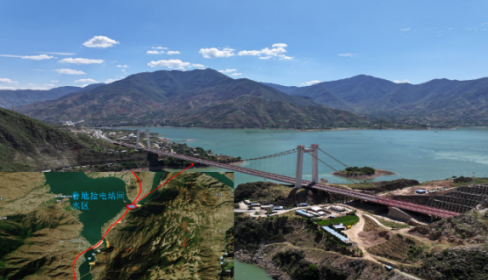
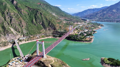
The main span of the Taoyuan Jinsha River Grand Bridge is a 636-meter double-tower, single-span suspension bridge with a steel box girder. The overall bridge layout is as follows: a (40 + 50 + 40) meter steel box girder bridge + a segment of roadway + a 636-meter steel box girder suspension bridge + a [(30 + 35 + 30) + (40 + 40 + 30)] meter steel box girder bridge, with a total length of 1095.0 meters.
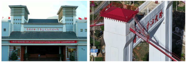
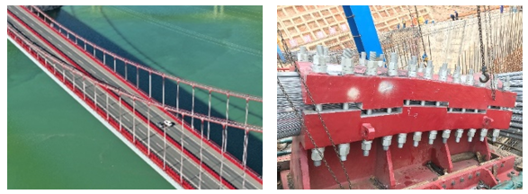
Figure 3. Actual View Photo of the Bridge After Completion-1.
Figure 4. Actual View Photo of the Bridge After Completion-2.
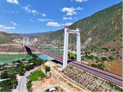
4.2. Cable Towers
The cable towers use a portal-frame reinforced concrete design, with the overall shape inspired by the " Bian Tun Culture "style. The tower columns have a Y-shaped thin-walled hollow cross-section. Thicker sections are added in areas of higher stress, such as where the upper and lower horizontal beams intersect. The base of the tower features a 3-meter solid section, and the foundation uses a composite system of bored piles and steel casing.
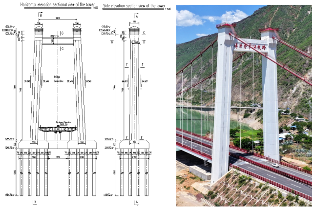
Figure 5. Actual View Photo of Cable Support Tower.
Figure 6. Design Drawings and Actual View Photos of Cable Support Tower.
The cable towers on the Dali bank have a total height of 75 meters, with the cross-section of the tower changing linearly from 5.5 m × 5.5 m at the top to 7.0 m × 5.5 m at the bottom. The towers on the Yongsheng bank have a total height of 70.5 meters, with the cross-section changing linearly from 5.5 m × 5.5 m at the top to 6.905 m × 5.5 m at the bottom. The solid section at the top of the towers has been widened to 6.8 meters in the longitudinal direction to accommodate the space required for the cable saddles.
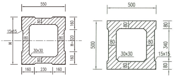
Both towers use a Y-shaped thin-walled hollow cross-section with a wall thickness of 0.8 meters. The foundation for the Dali bank towers consists of 2×16 φ2.2 m bored piles arranged in rows, designed as friction piles. The foundation for the Yongsheng bank towers consists of 2×9 φ2.2 m bored piles arranged in rows, designed as rock-embedded piles. Below are the cross-sections for the tower columns and the horizontal beams.
Figure 7. Typical Cross-Section View of Cable Support Tower.
4.3. Anchorages
Both banks use gravity-type anchorages with enlarged foundations, and the anchoring system employs high-strength steel tie rod anchorage. The anchorages are located beneath the approach bridges and follow a gravity-type anchorage with an enlarged foundation.
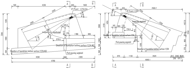
On the Dali bank, the anchorage foundation is supported by a combination of block stone soil, gravel soil, and silt. Given the relatively shallow embedding depth of the anchorage, the foundation is designed with a single sloped surface to enhance resistance to sliding and overturning, reduce maximum stress on the foundation during use, and minimize excavation volume. The shallow-buried gravity anchorage has a foundation positioned above the groundwater level, measuring approximately 67 meters in length, 60 meters in width, and 33 meters in height. Its bearing capacity and stability were verified through in-situ tests on site
| [7] | Song, G., Tang, H., Yuan, C. H., et al. (2019). In-situ test study on rock foundation of gravity anchorage for Taoyuan Jinsha River Bridge. Construction Materials World, 40(2), 23–26. |
[7]
.
On the Yongsheng bank, the anchorage foundation relies on block stone soil, gravel soil, and limestone as the primary bearing layers. Since the anchorage is situated in moderately weathered limestone, a rock-embedded structure is used to reduce the volume of the foundation work. The anchorage block is designed with a prestressed anchorage system, and the base cannot be uplifted due to the structural dimensions. A vertical steep slope is used between the saddle support foundation and the anchorage block. The anchorage measures approximately 60 meters in length, 50 meters in width, and 38 meters in height.
Figure 8. Anchorage Elevation Design Drawing.
In the front anchorage chamber, the length of the cable strands along the span direction is 20 meters, and the length of the high-strength steel tie rods inside the anchorage body is also 20 meters. The main cable strands are anchored via a cable anchorage connection structure, which connects to the prestressed anchorage structure.
The cable anchorage connection structure includes both single-cable and double-cable anchorage configurations:
Single-cable Anchorage: This configuration consists of 2 φ68 mm steel tie rods, which correspond to high-strength steel tie rods with a specification of 80 mm, anchoring one main cable strand.
Double-cable Anchorage: This configuration consists of 4 φ68 mm steel tie rods, which correspond to high-strength steel tie rods with a specification of 110 mm, anchoring two main cable strands.
4.4. Cable System
The bridge features two main cables, each composed of 91 parallel steel wire strands
| [8] | Li, D. D., Zhang, L., Wang, J. H., et al. (2024). Key technologies for cable erection of Taoyuan Jinsha River Bridge. Transport World, (11), 146–148. |
[8]
. Each strand is made up of 91 wires with a nominal diameter of Φ5.0 mm and a tensile strength of 1770 MPa, coated with a zinc-aluminum alloy. The main cables are designed with spans of 160 meters + 636 meters + 140 meters, with a central span ratio of 1/10, and the distance between the centers of the two main cables is 28.0 meters. The inner diameter of the main cable clamps is 503 mm, and the outer diameter is 509 mm. The main cables are protected using an active protection system consisting of "wrapped steel wire + wrapping tape + dry air dehumidification."
The hangers use parallel steel wire strands and are connected to the clamps and stiffening beams via pin joints. The long hanger pin joints are equipped with tin bronze bushings, while the short hanger pin joints in the central span area are equipped with bearing joints. The hangers consist of 91 wires with a nominal diameter of Φ5.0 mm and a tensile strength of 1770 MPa, covered with a double-layer PE sheath.
The main cable saddles use a combination of casting and welding with a single longitudinal rib structure. To reduce lifting and transport weight, the saddle body is divided into two halves, which are assembled with high-strength bolts after being lifted to the top of the tower. The total weight of the main cable saddle is 105 tons, with the saddle body weighing 55 tons. The maximum transport weight of a single saddle body is 27 tons, with a longitudinal length of 2.7 meters and a transverse width of 2.95 meters.
The spreader saddle is of the pendulum-type, constructed with a combination of casting and welding. The total weight of the spreader saddle is 145 tons, with the saddle body weighing 101 tons. The maximum transport weight of a single saddle body is 101 tons, with a longitudinal length of 4.8 meters, a transverse width of 5.1 meters, and a height of 4.3 meters.
Figure 9. Actual View Photo of Cable System.
4.5. Stiffening Girders and Deck System
The bridge uses a single-span streamlined flat steel box girder structure, with a total length of 634.4 meters. Based on segment model testing and considering the manufacturing
| [9] | Gong, S. P., Zeng, X. P., & Fu, X. L. (2022). Installation construction technology for stiffening girders of long-span suspension bridges in plateau mountainous areas. Chinese Science and Technology Journal Database (Citation Edition) Engineering Technology, (5), p. 5. |
[9]
, processing, and installation conditions of the steel box girder, a single-chamber steel box girder section with wind deflectors was selected. The girder has a total width of 31.4 meters, with a clear height of 3.0 meters at the bridge axis and a 2% cross slope on the top surface. The bridge is divided into 53 segments, with four different types of girder segments. Among these, 48 segments are standard girder sections with a maximum lifting weight of 162.9 tons, and the length of each standard segment is 12.2 meters.
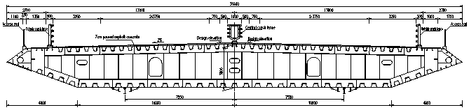
Figure 10. Standard Cross-Section Design Drawing of Main Girder.
The steel girder features two vertical web plates, aligned with the suspension point ear plates. Wind deflectors are positioned on the outer side of the longitudinal web plates, with a transverse spacing of 28.0 meters between the web plates. The steel box girder is designed as an orthotropic steel bridge deck, with a deck thickness of 16 mm and a bottom plate and side sloping bottom plate thickness of 10 mm. To meet the requirements for stress and stability, the bottom plate in the cable tower section is locally thickened to 16 mm.
The deck is reinforced with U-shaped ribs, with the U-ribs on the deck having a thickness of 8 mm and a center-to-center spacing of 600 mm. The bottom plate is also reinforced with U-shaped ribs, which are 6 mm thick with a center-to-center spacing of 800 mm. Each segment of the steel box girder has a transverse diaphragm every 3.1 meters, with diaphragms being 10 mm thick where there are no hangers and 12 mm thick where hangers are present.
The bridge is equipped with two pairs of vertical supports, two pairs of transverse wind-resistant supports, and four sets of longitudinal dampers. The vertical supports, wind-resistant supports, and dampers are located along the bridge axis direction on the bearing platforms of the towers on both banks.
5. Key Technologies
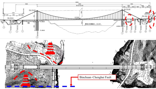
5.1. Seismic Design Technology
The design utilizes a comprehensive seismic design approach featuring:
1) High-strength coarse-diameter reinforcement
2) Beam-end damping and constraint systems
3) Steel casing at the top of piles
These measures are implemented to withstand the strong seismic effects from nearby active faults.
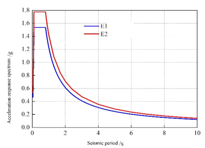
Figure 11. Horizontal Design Seismic Response Spectrum
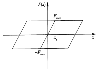
Figure 12. Simulation of Friction Effects in the Longitudinal Direction of the Main Bridge Stiffening Girder Bearings.
(i) During the design phase of the bridge, a comparison of reinforcement for the cable towers was conducted. Two options were considered:
1) Dual R32 mm rebar with a spacing of 160 mm, using HRB400 steel
2) Single R40 mm rebar with a spacing of 140 mm, using HRB500 steel
By meeting the structural stress requirements, the amount of main reinforcement used in the cable towers was reduced by 12.0%.
(ii) Four sets of liquid viscous dampers are installed at the ends of the stiffening girder. The dampers have a damping coefficient of 2000 kN·s/m, a velocity index of 0.3, and a maximum displacement of ±760 mm.
These dampers effectively constrain the longitudinal displacement of the main girder under high seismic intensity and high wind speed, reducing the length of expansion joints. As a result, the size of the expansion joints has been reduced from 3200 mm, without seismic measures, to 1520 mm.
(iii) By using a relatively lighter steel box girder, the structural mass is reduced, which in turn decreases the structural dynamic response.
The maximum cable force in the main cable can be reduced from 184,897 kN with the "composite girder + steel truss" design to 114,125 kN with the steel box girder design, a reduction of 38.3%. This reduction directly decreases the engineering scale of the main cable, cable towers, and anchorages.
(iv) The cable tower pile foundations use 2.2-meter-diameter large-diameter piles. A 25 mm thick, 9.8-meter-long Q355 steel casing is added to the top of the pile foundation, extending 2.3 meters into the bearing platform.
This technology allows the top of the pile foundation to reduce the main reinforcement from dual R32 mm bars with a spacing of 150 mm to a single R32 mm bar with a spacing of 125 mm, resulting in a 40% reduction in the main reinforcement of the pile foundation.
5.2. Integrated Application of "Anchor Structure Foundation Selection and Spreader Saddle Design" Technology
This approach focuses on:
1) Selecting Appropriate Anchor Structure Foundations: Choosing the right type of anchor foundation to optimize stability and reduce the need for extensive excavation in slope areas.
2) Designing Spreader Saddles: Implementing spreader saddle designs that facilitate effective load distribution and support, minimizing the impact on surrounding areas.
3) These technologies collectively contribute to reducing slope excavation volumes and managing dry operations for anchor foundation pits in high water level conditions.
(i) Using spreader saddle designs to reduce the vertical anchoring angle of the main cables and elevate the base elevation helps achieve dry operations for anchor foundation pits
| [10] | Duan, X. H., Xu, A. H., Luo, G. C., et al. (2020). Dynamic stability analysis of gravity anchor retaining slope under seismic action. Soil Engineering and Foundation, 34(2), 5. https://doi.org/CNKI:SUN:TGJC.0.2020-02-022 |
[10]
. To prevent vibration from the edge span's main cable from affecting the anchoring system and facilitate the installation of the main cable strands, a cable-turn saddle will be placed between the edge span and the anchorage span. This setup allows the main cable to be anchored at the anchor surface after turning downward.
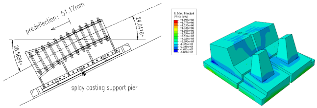
Due to the downward angle of the main cable relative to the edge span, the anchorage system and the depth of the foundation base are increased. To maintain stability during cable strand erection, the turning angle of the main cable within the saddle typically needs to be over 16°. The Taoyuan Jinsha River Bridge uses a spreader saddle structure where the vertical main cable achieves the saddle's support requirements with a small turning angle, avoiding the transmission of edge span cable vibrations to the anchorage span, thus preventing fatigue issues in the anchoring system.
The spreader saddle design results in a deflection of the main cable from 24.042° to 28.568° in the bridge's operational state, with a deflection angle of 4.526°. When using a conventional spreader saddle, the main cable's incident angle at the edge span is 28.562°, with a turning angle of 17.463° in the saddle.
Figure 13. Anchorage Stress Contour Plot.
Compared to the spreader saddle scheme, the spreader saddle design allows for an elevation increase of approximately 19.3 meters for the foundation base. This means that the foundation base elevation in the spreader saddle scheme is above the groundwater level, whereas the foundation base elevation in the spreader saddle scheme is below the water level. Using the spreader saddle design between the edge span and the anchorage span ensures that the foundation base is above the reservoir's elevated water level, reducing the need for pit waterproofing measures.
(ii) Utilizing a strip footing as the anchor foundation structure reduces disturbances to the slope at the Dali shore anchorage.
The Dali shore anchorage is located within a seismic fault zone where the rock mass consists primarily of gravel and silty soil, resulting in poor slope stability and a high risk of collapse during excavation disturbances
| [11] | Jiang, W. P., Xing, E. W., Du, W. J., et al. (2019). Bearing performance analysis of pile foundation for highway suspension bridge cable tower under complex geological conditions. Highway Engineering, 44(6), 5. https://doi.org/10.19782/j.cnki.1674-0610.2019.06.006 |
[11]
. To mitigate disturbances to the right slope, two main measures are implemented in the design:
1. Using a spreader saddle design to elevate the foundation base by 19.3 meters, thereby reducing the need for three levels of slope protection.
2. Increasing the length of the anchorage to reduce its lateral width. The anchorage's lateral dimensions are adjusted to accommodate the anchoring system's requirements, while the longitudinal dimensions are increased to meet both the vertical bearing capacity and the longitudinal stability needs.
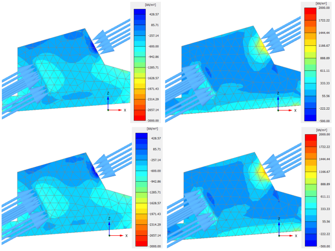
A strip footing gravity anchor foundation is employed on the thick cover layer to minimize disturbances to the slope, thereby reducing the engineering volume required for slope support
| [12] | Dan L, Tian M, Du W, et al. Static and Dynamic Stability Analysis of the Gravity Anchorage Slope Using the Three Dimensional Finite Element Method [J]. Earth and Environmental Science, 2019. https://doi.org/10.1088/1755-1315/304/4/042037 |
[12]
.
Figure 14. Stress Contour Plot of Anchorage at Dali Bank.
(iii) Using embedded rock strip footing foundations for the anchorages at the Yongsheng shore reduces excavation work. The Yongsheng shore anchorage is situated on shallow bedrock with underlying moderately weathered limestone, which has a vertical bearing capacity of 1200 kPa. Given the shallow depth of the bedrock, a gravity-type embedded rock anchor is used
| [13] | LU Zhiqiang, CHEN He, ZHANG Yonghua, et al. Study on Bearing Mechanism of Gravity Anchorage Based on Numerical Simulation [J]. Journal of Highway and Transportation Research and Development, 2021, 38(8): 67-74. |
[13]
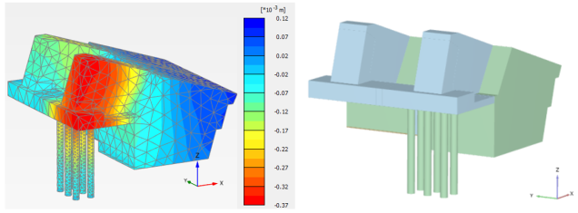
. The anchorage's anchoring body bottom is designed with an embedded structure to minimize excavation for the anchorage pit and reduce the volume of concrete required for the anchorage.
Figure 15. Stress Contour Plot and 3D Diagram of Anchorage at Yongsheng Bank
5.3. Installing Metal Sealing Airbags at the Junction of Suspension Bridge Cables and Anchor Heads to Block Rainwater and Improve Cable Durability
For the common challenge of waterproofing suspension cable anchor heads, an innovative metal airbag is installed between the suspension cable and the anchor head. The airbag is made from high-strength aluminum alloy, combining soft metal with multi-layer polymer materials to form an inflatable seal bag. It is equipped with high-temperature-resistant waterproof films on both sides for sealing the cable end. Rubber sealing rings are used to adjust the gaps between the cable conduit and the aluminum alloy airbag.
Construction Steps:
1. Attach the stainless steel cylinder to the lower anchor head connection cylinder.
2. Install the high-strength aluminum alloy airbag at the top and inflate it to a pressure of 0.3 MPa.
3. Maintain the pressure for 30 seconds, then close the air source and remove the air tube.
4. Install a sealing rubber ring at the outlet and finally seal it with polyurethane sealant.
This design effectively addresses the waterproofing issue of suspension cable anchor heads, enhancing the durability of the suspension cables.
Figure 16. Installation of Metal Sealing Airbags on Suspender Cables.
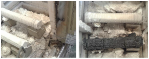
5.4. Using Ceramic Composite Insulation Wraps as High-Temperature Thermal Barriers for Main Cables and Hangers to Enhance Cable Heat Resistance
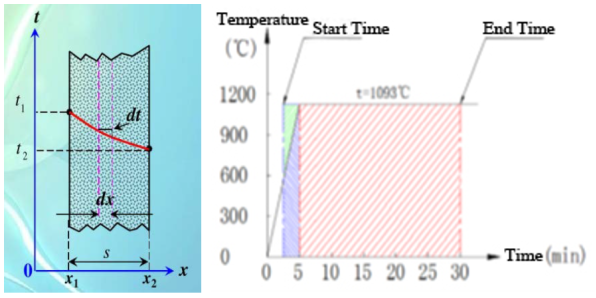
On the inner side of the main cable’s dehumidification system wrap, an additional layer of ceramic composite insulation wrap is applied. High-temperature-resistant grouting material is poured inside the anchor heads, and high-temperature fire-resistant coatings are applied to the exterior of the hanger anchor heads. For the section of the HDPE outer layer of the hanger cables within 8 meters of the bridge deck, the entire area is protected with ceramic composite insulation wrap. This protective setup allows the main cables and hangers covered with high-temperature-resistant protection to withstand environments up to 1100°C. The surface temperature of the cables does not exceed 300°C within 30 minutes and maintains fire resistance for over 3 hours. Additionally, the hanger anchors can support loads for more than 30 minutes at 300°C and 45% of their tensile strength, greatly enhancing the disaster resistance of the cable system.
Figure 17. High-Temperature Testing of Thin-Film Fire-Resistant Coatings and New Ceramic Composite Insulation Wraps.
Figure 18. Calculation of Thickness for High-Temperature Protective Wrap.
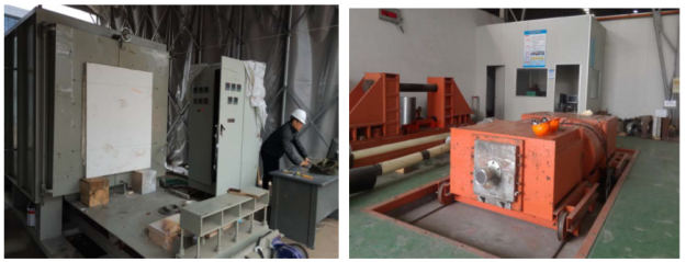
Figure 19. High-Temperature Mechanical Performance Testing.
The specific implementation plan is as follows:
1. Main Cable Protection
Protection Range: Main cables with a centerline height ≤ 8 meters from the bridge deck.
Measures:
Add a layer of high-temperature protective wrap between the Φ4 galvanized steel wires and the protective wrapping tape of the main cable.
2. Cable Clips and Cable Sleeves
Protection Range: Cable clips within 8 meters of the bridge deck in the middle span.
Measures:
Apply high-temperature resistant paint to the exterior surfaces of cable clips and clip bolt assemblies.
3. Suspension Cable Protection
Protection Range: Lower end anchors and upper end anchors of suspension cables with a total length of less than 8 meters in the middle span.
Measures:
Use high-temperature anchoring material inside the anchors and apply high-temperature paint to the exterior of the anchors.
Wrap the suspension cable surface with high-temperature protective wrap and cover it with 2mm stainless steel pipe (painted on the surface).
Install high-strength aluminum alloy airbag sealing devices at both ends of the 2mm stainless steel pipe on the suspension cable for effective sealing of the high-temperature protection structure.
4. Cable Clips and Anchor Heads
Protection Range: 30 sets of cable clips and 264 suspension cable anchors.
Measures:
Apply expanding fire-resistant paint. The paint should be suitable for outdoor use and provide good high-temperature performance.
Main Construction Steps:
Mixing: Mix the high-temperature paint according to the required ratio for outdoor use.
Painting: Apply the paint evenly to the surface of the components manually.
Sanding: Use an angle grinder to sand and smooth the paint layer, ensuring a smooth and defect-free surface.
5.5. Conducting Field Tests and Optimizing Design Parameters
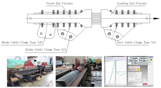
(ⅰ) Main Cable Steel Wire New Material Friction Test and Optimization of Clamp and Scatter Saddle Bolt Arrangement
During the project design phase, there was limited experience with the application of zinc-aluminum alloy coated steel wires. To verify whether the friction coefficient of μ=0.15, as recommended by the standards, is applicable to the materials used in this bridge, a slip resistance friction test was conducted between the cable clamps and the zinc-aluminum alloy coated steel wires.
The test main cable consisted of 91 strands of 5-91 zinc-aluminum coated prefabricated parallel wire strands, with a length of 6.5 meters. The inner surface of the test cable clamps was sandblasted (Sa3.0) and then coated with arc-sprayed zinc, with a thickness of 200 microns. The test was divided into two types: SJ1 and SJ5. The test cable clamps and braking cable clamps were connected to the loading-end fixture and the fixed-end fixture, respectively. The non-cable-held section in the middle was shaped with the assistance of a steel band. The assembled main cable had SJ1 and SJ5 cable clamps installed on one end as braking cable clamps, and an SJ1 cable clamp installed on the other end as the test cable clamp. The test was conducted to determine the maximum slip resistance force of the SJ1 test cable clamp and calculate the friction coefficient between the cable clamp and the main cable.
The main steps of the test were as follows:
(1) Installation: Install SJ1 and SJ5 clamps at one end as braking clamps and SJ1 at the other end as the test clamp. Position the test clamp and fixture at the calibrated location on the main cable, insert bolts and nuts, and place a small pressure sensor under the nuts to measure bolt axial force. Then, pre-tighten the bolts preliminarily.
(2) Initial Pre-tightening: Pre-tighten the bolts of the test clamp to 20%-30% of the designed pre-tightening force, and apply a pre-load to the test clamp to eliminate any instability in the cable strands caused by wire bending.
(3) Final Pre-tightening and Loading: After unloading the initial load, pre-tighten all bolts to the designed pre-tightening force and leave them for 12 hours. Retighten all bolts once more after allowing the bolt force to stabilize. Finally, use a hydraulic cylinder to uniformly apply the maximum load to the loading-end fixture.
Figure 20. Anti-Slip Test Photo of Cable Clamp.
Based on the calculation method provided in Section 11.4 of the "Highway Suspension Bridge Design Code" (JTGT D65-05-2015) for the slip resistance coefficient of cable clamps
| [14] | JTG/T D65-05-2015. Specification for Design of Highway Suspension Bridges. |
[14]
, the formula used is: μ=2.8·P
tot/F
tot. Through the tests conducted, the friction coefficient μ\muμ between the cable clamps and the steel wires for this bridge was determined to be 0.22, which is higher than the standard value of 0.15.
Table 1. Anti-Slip Test Results of Cable Clamp.
Test Content | Code Requirements | Experimental Saddle SJ1 | Experimental Saddle SJ5 |
Maximum Slip Resistance (kN) | / | >5201 | >1789 |
The Friction Coefficient Between the Main Cable Wires and the Saddles | ≥0.15 | 0.228 | 0.222 |
(ⅱ) Determining the Bearing Capacity of Pile Foundations in Deep, Water-Rich Soil Layers in Seismic Zones Using the Self-Balancing Method On-Site Testing
| [15] | GB/T 50266-1999, Standard for test methods of engineering rock masses [S], 1999. |
| [16] | GB 50007-2011, Code for design of building foundation [S], 2011. |
| [17] | Dan, L. Z., Yang, Z., Tian, M., Zou, H. Q., Wang, J. H., & Jiang, W. P. (2022). Deformation monitoring and analysis of gravity anchorage foundation in high-intensity near-field seismic zone with deep overburden. Sichuan Architecture, 42(5), 243–246. https://doi.org/10.3969/j.issn.1007-8983.2022.05.078 |
[15-17]
.
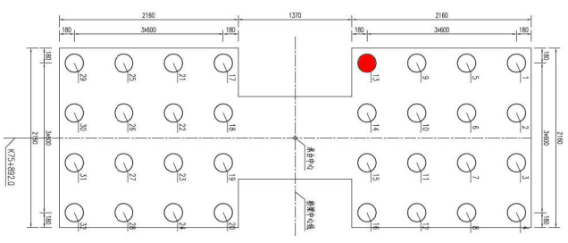
Due to the influence of the near-field effects of active faults, the vertical seismic forces on the bridge pile foundations are significant, and the pile foundations are situated in deep, water-saturated and unsaturated soil layers, leading to a complex loading condition. A static load test is planned for one of the pile foundations beneath the Dali bank tower to verify the pile's bearing capacity. The pile is a friction pile with a length of 65 meters and a diameter of 2.2 meters, with a single pile vertical bearing capacity of 20,000 kN. Based on the pile arrangement under the bearing platform and the current construction schedule, Pile No. 13 under the Dali bank tower is selected as the test pile for in-situ testing to verify the bearing capacity of the pile foundation after construction.
Figure 21. Test Pile Layout for Cable-Stayed Tower.
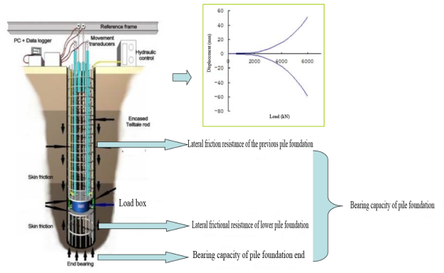
The test uses the self-balancing method, which relies on the principle of equilibrium achieved by the test pile's own reaction forces. A single-layer (or multi-layer) load cell is pre-embedded near the pile end or at a specific section of the pile. During loading, the load cell generates end resistance and upward side resistance below the load cell to counteract downward displacement. Above the load cell, downward side resistance is produced to counteract upward displacement. The reaction forces of the upper and lower pile sections are equal in magnitude but opposite in direction, achieving self-balancing loading for the test pile.
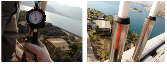
During the test, pressure is applied through a hydraulic pump on the ground. As the pressure increases, the load cell elongates, causing elastic (or plastic) deformation of the upper and lower pile sections, which gradually mobilizes the pile side and end resistance. The pressure applied by the load cell can be measured using a pre-calibrated hydraulic pressure gauge, while the displacement of the top and bottom plates of the load cell is measured using pre-set displacement rods or displacement wires with displacement sensors. This allows for the measurement of two Q-S curves for the upper and lower pile sections and the corresponding S-lgt curves. By using a reasonable data equivalence conversion method and bearing capacity determination method, the ultimate bearing capacity of the pile foundation, as well as the distribution of pile side and end resistance, can be determined.
Figure 22. Self - balanced method pile foundation bearing capacity test.
Principle: The load cell is designed based on the principle of equilibrium between the reaction forces of the upper and lower pile sections. The embedment elevation of the load cell is calculated accordingly. For the test pile with a total length of 65 meters, the load cell is placed at an elevation of 15.8 meters from the pile end. The load cell has a capacity of 2×13,500 kN. The static load test on the test pile is conducted after a curing period of 28 days for the drilled shafts. The load increments for the test pile are applied in stages, typically ranging from 1/10 to 1/12 of the estimated maximum load.
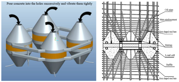
Field Installation: The main procedures include:
1) Pre-pouring Concrete for the Diversion Body: Pour concrete inside the diversion body.
2) Welding Load Cell and Reinforcement Cage: Weld the load cell to the reinforcement cage.
3) Additional Pipeline Arrangement: Arrange additional pipelines as required.
4) Lowering Reinforcement Cage: Lower the reinforcement cage into position.
5) Underwater Concrete Pouring: Pour concrete underwater as needed.
6) Curing Protection: Implement protective measures during the curing period.
Field Testing:
Once the pile's strength meets design requirements, the pile soil's curing period adheres to regulatory standards, and the pile's structural integrity is confirmed, the static load test begins. The primary activities of the test include:
1) Incremental Loading: Apply loads incrementally, with each load stage set at 1/10 of the maximum loading capacity, up to 1.2 times the allowable bearing capacity.
2) Incremental Unloading: Unload in stages, with each stage removing 3 loads' worth of load values.
3) Displacement Monitoring: Use a slow-load maintenance method for displacement observation. After applying each load stage, measure displacement at 5, 10, 15, 30, 45, and 60 minutes within the first hour. Continue measuring every 30 minutes until displacement stabilizes before proceeding to the next load stage.
4) Post-unloading Observation: After unloading to zero, observe for at least 2 hours, with measurement intervals similar to those during loading.
Figure 23. Schematic Diagram of the Test Loading Device for the Self-balanced Method.
Experimental Results:
The results of the test indicate that the 65-meter-long pile foundation meets the design bearing capacity requirements based on the parameters provided by geological drilling. Since the test pile will be used as a permanent engineering pile after the experiment, grout was applied to the load box area post-testing. The grouting treatment does not affect the vertical and horizontal load-bearing capacity of the pile.