Abstract
The paper considers the justification of a magnetic reconnection converter (MRC) based on a single-volume plasma (spheromak) with a variable β in the turbulent pumping (charging)/discharging phases of the thermodynamic duty cycle “α-dynamo – magnetic reconnection”. To obtain helpful energy, the proposed MRC uses a cyclic combination of two physical processes: 1) α-dynamo, generated by controlled turbulence, increases the global helicity H through the processes of twisting, writhing and bending of magnetic field (MF) flux tubes to the level of a local maximum (optimally global), which is determined by the plasma parameters, boundary conditions, tension of magnetic field lines, etc., and corresponding the MF strength and stochasticity in a limited plasma volume. At this stage of MF turbulent pumping, which corresponds to the α-dynamo physical process, β of the plasma will decrease to the minimum possible value with a corresponding increase in the accumulated "topological" energy of the MF; 2) when reaching the local (if possible global) maximum of the MF strength and stochasticity, turbulent magnetic reconnection (TMR) occurs in many places of the plasma, which lowers the state of the local (if possible global) maximum of the MF strength and stochasticity and increases the kinetic stochasticity of the plasma particles, accelerating and heating them, which is used in direct energy converters (DECs), and receiving coils of electrical energy. At this stage of turbulent discharge, which corresponds to multiple TMR, β of the plasma will increase to the maximum possible value with a corresponding increase in its kinetic and thermal energy. When the kinetic stochasticity of plasma particles decreases and reaches a minimum, the control system repeats the MF's turbulent pumping, generating multiple α-dynamo processes in the plasma, and the cycle repeats.
Keywords
Controlled Turbulence, α-dynamo, Magnetic Stochasticity, Magnetic Reconnection, Kinetic Stochasticity, Spheromak
1. Introduction
The escalating global energy consumption necessitates a paradigm shift towards sustainable and efficient energy generation technologies. Conventional methods, largely reliant on fossil fuels, pose significant environmental challenges, underscoring the urgent need for cleaner alternatives. Fusion energy, which harnesses the power of nuclear fusion reactions, holds immense promise as a virtually inexhaustible and environmentally benign energy source. However, realizing the full potential of fusion requires overcoming significant scientific and engineering hurdles, particularly in achieving sustained high-gain operation and efficient energy extraction. Traditional approaches often involve complex systems for converting the thermal energy produced by fusion reactions into electricity, typically through heat exchangers and turbines. These indirect conversion methods inherently suffer from thermodynamic limitations, motivating the exploration of novel plasma-based energy conversion concepts that aim for more direct routes to electricity generation. The proposed Magnetic Reconnection Converter (MRC) represents an innovative concept in this direction, aiming to directly convert the energy stored in a plasma's (conducting fluid in general) magnetic field into electrical power, potentially offering advantages in terms of efficiency and the compactness of the energy conversion system.
The core innovation of the MRC lies in its utilization of a cyclical process within a single, confined plasma volume, specifically a spheromak
. This thermodynamic cycle strategically combines two fundamental plasma physics phenomena: the α-dynamo effect and turbulent magnetic reconnection (TMR). The α-dynamo effect serves as the "charging" mechanism, where turbulent plasma motions generate and amplify magnetic fields, effectively storing energy in a topological form (analogy of heat source in Carnot cycle). This is followed by a "discharging" phase driven by TMR, a process where the stored magnetic energy is rapidly released and converted into kinetic and thermal energy of the plasma particles (as an analogy of helpful work in the Carnot cycle). The MRC concept envisions harnessing this released energy directly as electrical power through different methods, such as inductive coupling with receiving coils
,
E×B cooling in poloidal and toroidal configurations with external electrodes
| [2] | Rax J.-M., Kolmes E.J. and Fisch N.J. Efficiency and Physical Limitations of Adiabatic Direct Energy Conversion in Axisymmetric Fields. PRX Energy 4, 013007 (2025), p. 15, https://doi.org/10.1103/PRXEnergy.4.013007 |
[2]
, Traveling Wave Direct Energy Converter
| [3] | Takeno H. et al. A Study of Miniaturization of Traveling Wave Direct Energy Converter for Loading on a Spacecraft, TRANSACTIONS OF THE JAPAN SOCIETY FOR AERONAUTICAL AND SPACE SCIENCES, AEROSPACE TECHNOLOGY JAPAN, 2016, Volume 14, Issue ists30, Pages. Pb_105-Pb_109, Released on J-STAGE September 30, 2016. https://doi.org/10.2322/tastj.14.Pb_105 |
| [4] | Takeno H. et al., Deceleration in a traveling wave direct energy converter for advanced fusion, Fusion Eng. Des. 83 (2008) 1696–1699. https://doi.org/10.1016/j.fusengdes.2008.06.046 |
| [5] | Tarditi A. et al. “Progress Towards the Development of a Traveling Wave Direct Energy Converter for Aneutronic Fusion Propulsion Applications.” (2015). 9 p. https://doi.org/10.2514/6.2015-3861 |
[3-5]
, and Plasma Dynamic Converter
| [6] | Takeno H. et al. Recent Advancement of Research on Plasma Direct Energy Conversion, Plasma and Fusion Research, 2019, Volume 14, Pages 2405013, Released on J-STAGE February 22, 2019. 7 p. https://doi.org/10.1585/pfr.14.2405013 |
[6]
.
The spheromak (SPH) configuration
, a compact toroidal plasma structure with self-generated magnetic fields, is proposed as the ideal environment for this thermodynamic cyclic energy conversion process. Its closed magnetic field lines facilitate the confinement of the plasma and the buildup of magnetic energy during the charging phase, while its inherent properties may also promote the onset of turbulent magnetic reconnection for efficient energy release.
As for the structure of this paper, our goal is to the justification of a magnetic reconnection converter (MRC) based on a single-volume plasma (spheromak) with a variable β (relation of plasma to magnetic field pressures) in the turbulent pumping (charging)/discharging phases of the thermodynamic duty cycle “α-dynamo – magnetic reconnection”, and it is a continue of work
. This paper aims to provide a comprehensive theoretical justification for the proposed MRC concept. It will delve into the fundamental plasma physics principles underpinning the device's operation, including a short explanation of the α-dynamo effect, turbulent magnetic reconnection (TMR), and the properties of spheromak plasmas that are considering in Section 2. The framework and analogies of MRC thermodynamic duty cycle with Carnot cycle, and MRC direct energy converter (DEC) with electrical machine are substantiated in Section 3. A mathematical model describing the evolution of key plasma parameters during the MRC cycle will be proposed in Section 4, providing a framework for quantitative analysis of its performance. Furthermore, conceptual diagrams illustrating the device architecture and its operational cycle will be presented to aid in visualizing the concept in Section 5. Finally, the work will discuss the potential challenges and feasibility of this novel energy conversion approach, laying the groundwork for future research and development efforts considering in conclusion and discussion Section. In the Appendixes A-E will be presented illustrative materials to this paper.
At the writing of this paper, the author used the generative artificial intelligence chatbot Gemini, developed by Google.
2. Theoretical Foundations
2.1. The α-Dynamo Effect in Plasmas
The α-dynamo effect is a fundamental process in magnetohydrodynamics (MHD) that explains the generation and sustenance of large-scale magnetic fields in electrically conducting fluids, such as plasmas, through the action of helical turbulent motions
| [12] | Hubbard A., Del Sordo F., Kapyla P. J., Brandenburg A. The α effect with imposed and dynamo-generated magnetic fields. Monthly Notices of the Royal Astronomical Society, Volume 398, Issue 4, October 2009, Pages 1891–1899, https://doi.org/10.1111/j.1365-2966.2009.15108.x |
| [13] | Tzeferacos, P., Rigby, A., Bott, A. et al. Laboratory evidence of dynamo amplification of magnetic fields in a turbulent plasma. Nat Commun 9, 591 (2018). https://doi.org/10.1038/s41467-018-02953-2 |
| [14] | Mizerski K. A, Yokoi N, Brandenburg A. Cross-helicity effect on α-type dynamo in non-equilibrium turbulence. Journal of Plasma Physics. 2023; 89(4): 905890412. https://doi.org/10.1017/S0022377823000545 |
| [15] | Tobias SM. The turbulent dynamo. Journal of Fluid Mechanics. 2021; 912: P1. https://doi.org/10.1017/jfm.2020.1055 |
[12-15]
. In a turbulent plasma, fluctuating plasma velocity and MFs interact in a complex manner. When the turbulence possesses a net helicity (a measure of the correlation between velocity and vorticity, or equivalently, between velocity and magnetic field fluctuations), it can generate a mean electromotive force
E=⟨v × b⟩ that is aligned with the mean magnetic field
B . This relationship is often expressed as
E=αB, where α is the alpha coefficient
. The alpha coefficient's sign and magnitude are directly related to the helicity of the turbulence. Helical turbulent motions can effectively twist and fold magnetic field lines. This complex intertwining of field lines leads to the conversion of kinetic energy from the turbulent flow into magnetic energy, resulting in the amplification of the magnetic field on large scales. To increase the α-dynamo effect, we can apply the super-linear Richardson diffusion
| [17] | Lazarian A., Eyink G. L., Jafari A., Kowal G., Li H., Xu S., Vishniac E. T. 3D turbulent reconnection: Theory, tests, and astrophysical implications, Phys. Plasmas 27, 012305 (2020). 63 p. https://doi.org/10.1063/1.5110603 |
[17]
. In turbulent flows, Richardson diffusion describes the accelerated spreading of particles or fluid elements compared to the linear scaling with time observed in normal diffusion. This enhanced diffusion can play a significant role in the context of the α-dynamo by facilitating the spatial distribution of the magnetic field generated by the turbulent motions throughout the plasma volume, potentially leading to a more globally stochastic magnetic field. Furthermore, the concept of self-generated or self-sustaining physical processes within the plasma is crucial for the continuous operation of the α-dynamo
| [18] | Zhang J., Xu S., Lazarian A., Kowal G. Particle acceleration in self-driven turbulent reconnection, Journal of High Energy Astrophysics 40 (2023). 10 p. https://doi.org/10.1016/j.jheap.2023.08.001 |
| [19] | Beg R., Russell A., Hornig G. Evolution, Structure, and Topology of Self-generated Turbulent Reconnection Layers. The Astrophysical Journal, 940: 94 (32pp), 2022 November 20. https://doi.org/10.3847/1538-4357/ac8eb6 |
| [20] | Oishi J., Mac Low M., Collins D., Tamura M. Self-generated Turbulence in Magnetic Reconnection. The Astrophysical Journal Letters, 806: L12 (5pp), 2015 June 10. http://dx.doi.org/10.1088/2041-8205/806/1/L12 |
[18-20]
. Non-linear interactions within the turbulent flow can, under certain conditions, maintain the helical nature of the turbulence, allowing the dynamo effect to persist and continuously pump energy into the magnetic field. As controlled methods of these non-linear interactions we may apply drift-wave and interchange instabilities
.
The evolution of the mean magnetic field
B in a conducting fluid, including the effects of the α-dynamo, is governed by the mean-field induction equation
:
where V is the mean plasma velocity, η is the magnetic diffusivity (a measure of the plasma's resistance to magnetic field diffusion), and J=∇×B/μ0 is the current density. The crucial term here is ∇×(αB), which represents the contribution of the α-dynamo effect to the temporal change of the magnetic field. A non-zero α coefficient, arising from helical turbulence, can lead to the growth of the magnetic field over time, counteracting the dissipative effects of magnetic diffusion represented by the ηJ term.
The α-dynamo effect is also intimately connected to the generation and evolution of magnetic helicity
H, a topological quantity that measures the linkage and knottedness of magnetic field lines. Magnetic helicity may be defined through MF parameters as
H=∫A⋅BdV, where
A is the magnetic vector potential of MF
B=∇×A. The α-dynamo process can drive the transfer of energy into magnetic helicity, contributing to the complex topological structure of the magnetic field envisioned in the MRC's charging phase. The evolution equation for magnetic helicity involves terms related to resistive dissipation and the electromotive force, which in the presence of an α-dynamo, will reflect the continuous generation of helicity. Another way the global magnetic helicity
H, which determines the degree of tangling or braiding of MF lines and flux tubes may be determined through 3 main components: 1) twisting, 2) linking, and 3) writhing
:
(2)
where the integral is performed over all space where exists magnetofluid with a magnetic field, and each index labels a vortex tube of magnetic flux
Γi (
u,
ω are velocity and vorticity of this magnetic flux, and
dV a volume element), and the first term of right side (2) is mutual helicity due linking
i-j flux tubes (or lines) with factor
Kij, and the second term of right side (2) is self-helicity due twisting with factor
Twi and writhing with factor
Wri. Magnetic helicity is practically constant with the ideal moving of the medium (continuous deformations of flow tubes). Twisting
Twi is a changeable local parameter while linking
Kij and writhing
Wri are non-local parameters of MF flux tubes (lines). At stretching flux tubes (lines) of a MF, writhing can turn into twisting. At compressing flux tubes (lines) of a MF, it is vice versa. Magnetic helicity is constant
H = const if resistivity of medium
η = 0 and absence of helical turbulence. Twisted flux ropes store free magnetic energy, which may be released either in individual flux ropes in the nonlinear phase of the ideal kink instability, or through interaction of multiple twisted flux ropes
. In the former case, the field relaxes to a state of minimum magnetic energy through internal magnetic reconnections as well as reconnection with ambient untwisted field lines. In the latter case, multiple flux ropes reduce their energy through reconnecting into a single flux rope. For two flux ropes, the energy release is found to be substantially greater if the flux ropes initially have opposite currents (twisted in reverse senses) than if the currents are in the same direction
| [24] | Parker E. N. Magnetic reconnection and the lowest energy state, Earth Planets Space, 53, 2001. pp. 411–415, https://earth-planets-space.springeropen.com/articles/10.1186/BF03353250 |
| [25] | Yamada M., Kulsrud R., Ji H. Magnetic Reconnection, PPPL-4457. Information Services Princeton Plasma Physics Laboratory, 2009. 63 p. https://www.osti.gov/biblio/965275 |
| [26] | Pontin D. I., Horning G. The Parker problem: existence of smooth force-free fields and coronal heating, Springer, 2020. 54 p. https://doi.org/10.1007/s41116-020-00026-5 |
[24-26]
. This is because the former configuration has zero helicity, and hence the relaxed state has lower energy. However, the opposite-twisted flux ropes are much less likely to relax and release the free energy, since neither the toroidal or poloidal magnetic field components reverse at the interface between the flux ropes, and there is no obvious way - apart perhaps from a strong external perturbation - in which magnetic reconnection could be initiated.
Turbulence is the essential ingredient for the α-dynamo effect to operate. The fluctuating velocity and magnetic fields within the turbulent plasma are responsible for generating the mean electromotive force that sustains the large-scale magnetic field. The statistical properties of the turbulence, particularly its intensity and helicity, directly determine the magnitude and sign of the alpha coefficient. A high level of helical turbulence will generally lead to a larger alpha coefficient and a more efficient generation of magnetic field. Richardson diffusion, with its characteristic scale-dependent diffusion coefficient, can play a significant role in the spatial dynamics of the magnetic field generated by the α-dynamo process. The accelerated spreading of magnetic field lines due to Richardson diffusion in the turbulent plasma can facilitate the development of a globally stochastic magnetic field throughout the spheromak volume, as proposed in the MRC concept. This stochasticity is crucial for the subsequent turbulent magnetic reconnection phase. Achieving and maintaining turbulence with specific properties, such as a dominant helicity and a desired level of intensity, is a key technological challenge for the successful implementation of the MRC. The ability to control the self-generating / self-sustaining turbulence through helical Richardson diffusion would allow for optimization of the magnetic field pumping phase and the level of stored magnetic energy.
Also, to drive turbulence and subsequently an α-dynamo processes may use drift-wave and/or interchange instabilities
in a controlled manner. These specific instabilities have characteristics that might be better suited for controlled energy conversion. Drift waves are low-frequency electrostatic waves driven by pressure gradients in magnetized plasmas. They are ubiquitous in confined plasmas and can readily generate turbulence. The frequency and wavelength of drift waves are related to plasma parameters, offering potential knobs for control. Interchange instabilities arise in plasmas confined by curved magnetic fields where the pressure gradient is unfavorable to the magnetic field curvature. They can lead to the rapid transport of plasma across magnetic field lines and generate significant turbulence, often with a "flute-like" structure. The spatial structure of drift waves and interchange modes is often linked to the plasma geometry and magnetic field configuration and have threshold conditions for their onset and growth. Maintaining the plasma parameters within the unstable regime while also allowing for controlled transitions to reconnection and back to field amplification could be tricky. The non-linear evolution of these instabilities can be complex, leading to saturation of turbulence and potentially unpredictable behavior of the α-dynamo. The interplay between the turbulence driven by these instabilities and the magnetic reconnection process itself needs careful consideration. The turbulence could affect the reconnection rate, and the energy released by reconnection could influence the stability and characteristics of the drift waves or interchange modes. Developing effective control mechanisms to initiate, sustain, modify, and quench these instabilities on demand will be a significant engineering challenge. This could offer some spatial control over where the dynamo action and subsequent reconnection occur. The turbulence generated by these instabilities can, under the right conditions, possess the necessary helicity to drive an α-dynamo. Control over the plasma parameters (density gradients
, temperature gradients
, magnetic field curvature
k, shear flows) could potentially influence the characteristics of the instabilities and the resulting turbulence, allowing for some degree of control over the α-dynamo process (growth rate, spatial structure of the generated field). Next, we will consider that for the proposed magnetic reconnection converter (MRC), as a strong external disturbance, we will use the physical process of the α-dynamo, applying the turbulent pumping through a super-linear Richardson cascade, self-generated/self-sustaining turbulence, drift-wave/interchange instabilities or their combinations.
2.2. Turbulent Magnetic Reconnection (TMR)
Magnetic reconnection is a fundamental process in plasma physics where magnetic field lines with opposite polarity break and reconnect, resulting in a rapid release of magnetic energy and a change in the magnetic field topology
| [22] | Pontin D. I., Priest E. R. Magnetic reconnection: MHD theory and modelling, Springer, 2022. 202 p. https://doi.org/10.1007/s41116-022-00032-9 |
| [27] | Ji H., Daughton W., Jara-Almonte J., Le A., Stanier A., Yoo J. Magnetic reconnection in the era of exascale computing and multiscale experiments, [physics. plasm-ph] 18 Feb 2022. 35 p. https://arxiv.org/abs/2202.09004 |
| [28] | Jafari A., Vishniac E. Introduction to Magnetic Reconnection, [astro-ph. HE] 15 Jun 2018. 32 p. https://doi.org/10.48550/arXiv.1805.01347 |
| [29] | Yamada, M. Review of the recent controlled experiments for study of local reconnection physics. Earth Planet Sp 53, 509–519 (2001). 12 p. https://doi.org/10.1186/BF03353263 |
| [30] | Yamada, M., Yoo, J., Jara-Almonte, J. et al. Conversion of magnetic energy in the magnetic reconnection layer of a laboratory plasma. Nat Commun. 5, 4774 (2014). 8 p. https://doi.org/10.1038/ncomms5774 |
| [31] | Yamada, M., Chen, LJ., Yoo, J. et al. The two-fluid dynamics and energetics of the asymmetric magnetic reconnection in laboratory and space plasmas. Nat Commun 9, 5223 (2018). 11 p. https://doi.org/10.1038/s41467-018-07680-2 |
| [32] | Dahlin J. T., Drake J. F., Swisdak M. Electron acceleration in three-dimensional magnetic reconnection with a guide field, Phys. Plasmas 22, 100704 (2015). 6 p. https://doi.org/10.1063/1.4933212 |
| [33] | Dahlin J. T. Prospectus on electron acceleration via magnetic reconnection, Phys. Plasmas 27, 100601 (2020). 13 p. https://doi.org/10.1063/5.0019338 |
| [34] | Chien A. et al. Direct measurement of non-thermal electron acceleration from magnetically driven reconnection in a laboratory plasma, [physics. plasm-ph] 25 Jan 2022. 13 p. https://doi.org/10.48550/arXiv.2201.10052 |
| [35] | Oka M. et al. Particle Acceleration by Magnetic Reconnection in Geospace, Space Science Reviews (2023) 219: 75. 36 p. https://doi.org/10.1007/s11214-023-01011-8 |
[22, 27-35]
. In laminar, resistive plasmas, the rate of reconnection is typically slow, as described by models like Sweet-Parker and Petschek
| [17] | Lazarian A., Eyink G. L., Jafari A., Kowal G., Li H., Xu S., Vishniac E. T. 3D turbulent reconnection: Theory, tests, and astrophysical implications, Phys. Plasmas 27, 012305 (2020). 63 p. https://doi.org/10.1063/1.5110603 |
| [22] | Pontin D. I., Priest E. R. Magnetic reconnection: MHD theory and modelling, Springer, 2022. 202 p. https://doi.org/10.1007/s41116-022-00032-9 |
[17, 22]
. However, in turbulent plasma environments, the reconnection process can be significantly accelerated
| [36] | Eyink G., Aluie H. The breakdown of Alfven’s theorem in ideal plasma flows: Necessary conditions and physical conjectures. Physica D 223 (2006) 82–92 p. https://doi.org/10.1016/j.physd.2006.08.009 |
| [37] | Eyink, G., Vishniac, E., Lalescu, C. et al. Flux-freezing breakdown in high-conductivity magnetohydrodynamic turbulence. Nature 497, 466–469 (2013). https://doi.org/10.1038/nature12128 |
| [38] | Jafari A., Vishniac E. Topology and stochasticity of turbulent magnetic fields. Phys Rev E. 2019 Jul; 100 (1-1): 013201. https://doi.org/10.1103/PhysRevE.100.013201 |
| [39] | Jafari A., Vishniac E., Vaikundaraman V. Magnetic stochasticity and diffusion, [astro-ph. HE] 20 Aug 2019. 8p. doi: https://doi.org/10.1103/PhysRevE.100.043205 |
| [40] | Jafari A., Vishniac E., Vaikundaraman V. Statistical Analysis of Stochastic Magnetic Fields, [astro-ph. HE] 14 Jan 2020. 17 p. https://doi.org/10.1103/PhysRevE.101.022122 |
| [41] | Jafari A., Vishniac E. Power and spatial complexity in stochastic reconnection, [astro-ph. HE] 10 Apr 2020. 6 p. https://doi.org/10.1063/5.0009150 |
| [42] | Jafari, A. and Vishniac, E. Magnetic topology in fluids, 2019. 10 p. https://doi.org/10.48550/arXiv.1909.07325 |
| [43] | Jafari A., Vishniac E. Topological theory of physical fields, [astro-ph. HE] 8 Jan 2021. 13 p. https://doi.org/10.48550/arXiv.1909.04836 |
| [44] | Jafari A., Vishniac E., Xu S. Nanoflare Theory Revisited. The Astrophysical Journal, 906: 109 (10pp), 2021 January 10. https://doi.org/10.3847/1538-4357/abca47 |
| [45] | Jafari A. Does Magnetic Reconnection Change Topology? [physics. plasm-ph] 30 Aug 2024. 10 p. https://doi.org/10.48550/arXiv.2408.13732 |
[36-45]
. Turbulence introduces small-scale fluctuations in the magnetic field and plasma velocity, which can lead to the formation of numerous, localized current sheets where reconnection can occur much more rapidly. The stochastic nature of the magnetic field in turbulent plasmas also increases the probability of oppositely directed field lines coming into close proximity, facilitating the onset of reconnection at multiple sites simultaneously. This distributed reconnection process can lead to a much faster and more efficient release of magnetic energy compared to single-site laminar reconnection
| [17] | Lazarian A., Eyink G. L., Jafari A., Kowal G., Li H., Xu S., Vishniac E. T. 3D turbulent reconnection: Theory, tests, and astrophysical implications, Phys. Plasmas 27, 012305 (2020). 63 p. https://doi.org/10.1063/1.5110603 |
[17]
. Developing a comprehensive mathematical model for turbulent magnetic reconnection (TMR) remains an active area of research in plasma physics. While classical models provide a foundation, they do not fully capture the complexities introduced by turbulence. Turbulent reconnection models often incorporate the effects of anomalous resistivity, which is enhanced by turbulence, leading to faster diffusion of the magnetic field and a higher reconnection rate. The energy release rate in turbulent reconnection is often parameterized by a dimensionless reconnection rate, which can be significantly larger than the values predicted by laminar models. This rate depends on factors such as the intensity and scale of the turbulence, as well as the magnetic Reynolds number of the plasma. The energy released during turbulent reconnection is primarily converted into kinetic and thermal energy of the plasma particles. This manifests as heating of the plasma and acceleration of charged particles to high energies. Particle acceleration can occur through several mechanisms, including the inductive electric field generated by the rapidly changing magnetic field during reconnection and stochastic acceleration due to interactions with turbulent fluctuations. The mathematical description of these processes often involves kinetic theory, which considers the velocity distribution of the plasma particles, in addition to the fluid description provided by MHD
| [17] | Lazarian A., Eyink G. L., Jafari A., Kowal G., Li H., Xu S., Vishniac E. T. 3D turbulent reconnection: Theory, tests, and astrophysical implications, Phys. Plasmas 27, 012305 (2020). 63 p. https://doi.org/10.1063/1.5110603 |
[17]
. Modeling the precise mechanisms and efficiency of particle acceleration during turbulent reconnection is crucial for understanding the energy balance in the MRC's discharge phase.
The onset of turbulent magnetic reconnection in the proposed MRC is likely governed by several factors, including the level of magnetic field stochasticity achieved during the turbulent pumping phase, the local plasma β, and the presence of current sheets or regions of strong magnetic shear within the spheromak. As the α-dynamo effect increases the stochasticity of the magnetic field, the tangled and intertwined field lines become more prone to encountering regions of opposite polarity in close proximity. When the level of magnetic field stochasticity reaches a critical threshold a local (if possible global) maximum of MF stochasticity, it can trigger the onset of widespread turbulent reconnection throughout the plasma volume. The plasma β, which reflects the ratio of plasma pressure to magnetic pressure, can also play a role. Regions with low β, where magnetic pressure dominates, might be more susceptible to reconnection events. Additionally, the presence of current sheets, where the magnetic field changes direction rapidly, can provide preferential sites for reconnection to initiate. Understanding the interplay of these factors is crucial for controlling the timing and intensity of the discharge phase in the MRC.
2.3. Spheromak Plasma Configuration
A spheromak is a compact toroidal plasma configuration where the magnetic field is primarily generated by internal plasma currents, resulting in a unique structure with linked poloidal and toroidal magnetic fields of comparable strength
. Unlike tokamaks, spheromaks do not require a central toroidal field coil, making them potentially simpler and more compact. Spheromaks exhibit a high degree of magnetic self-organization, tending to relax towards a minimum energy state while conserving magnetic helicity. They can achieve relatively high plasma densities and magnetic field strengths, making them attractive for fusion energy research. Key dimensionless parameters characterizing spheromaks include the magnetic Reynolds number (Rm), which represents the ratio of advective to diffusive transport of the magnetic field, and the Lundquist number (S), which is the ratio of the resistive diffusion time to the Alfvén time (the characteristic time for MHD waves to propagate). These numbers are crucial for understanding the stability and dynamics of spheromak plasmas. The magnetic field structure in a spheromak can often be approximated by a force-free configuration, where the Lorentz force
J×B is zero, meaning the current density
J is parallel to the magnetic field
B or
J = λB, where λ is a constant or a function of position. This configuration represents a state of minimum magnetic energy for a given magnetic helicity
H. Spheromaks can be susceptible to certain MHD instabilities, such as the tilt instability (where the spheromak rotates and destroys itself against the confinement vessel) and the shift instability (where the spheromak moves away from its equilibrium position). However, these instabilities can be mitigated through various techniques, including the use of conducting walls surrounding the plasma, external magnetic fields, and plasma shaping. The stability of the spheromak plasma will be a critical factor for the sustained and reliable operation of the proposed MRC, especially during the dynamic turbulent pumping and discharge phases. The spheromak configuration appears well-suited for the proposed MRC for several reasons. Its closed magnetic field lines provide an inherent mechanism for containing the plasma and allowing the magnetic field energy to build up during the α-dynamo -driven charging phase. The single-volume nature of the spheromak simplifies the overall device design compared to more complex, multi-component concepts. Furthermore, the potential for achieving high magnetic field energy density within a compact volume makes the spheromak an attractive candidate for a device aiming for significant energy release through magnetic reconnection. The inherent magnetic helicity of spheromaks might also play a beneficial role in facilitating the α-dynamo effect, as helical turbulence is crucial for its operation. The ability to generate and sustain a spheromak plasma with controlled turbulence and to trigger turbulent magnetic reconnection within it are key aspects that make this configuration relevant to the MRC concept.
2.4. Plasma β in Magnetic Confinement
Plasma β is a dimensionless parameter that quantifies the ratio of the plasma's kinetic pressure
p = ρkB T to the magnetic pressure
pB=B2/(2μ0) | [17] | Lazarian A., Eyink G. L., Jafari A., Kowal G., Li H., Xu S., Vishniac E. T. 3D turbulent reconnection: Theory, tests, and astrophysical implications, Phys. Plasmas 27, 012305 (2020). 63 p. https://doi.org/10.1063/1.5110603 |
| [22] | Pontin D. I., Priest E. R. Magnetic reconnection: MHD theory and modelling, Springer, 2022. 202 p. https://doi.org/10.1007/s41116-022-00032-9 |
[17, 22]
:
where ρ is the plasma density, kB is the Boltzmann constant, T is the plasma temperature, B is the magnetic field strength, and μ0 is the permeability of free space. Plasma β is a crucial parameter in magnetic confinement systems as it indicates the relative importance of the plasma's thermal energy compared to the energy stored in the magnetic field. A high β value signifies that the plasma pressure is a significant fraction of the magnetic pressure, suggesting an efficient utilization of the magnetic field for confinement. Conversely, a low β indicates that the magnetic field energy dominates. Plasma β also has a significant impact on plasma stability. Different types of MHD instabilities can be driven or suppressed depending on the value of β and its spatial profile within the plasma. For energy conversion devices like the proposed MRC, understanding and controlling plasma β is essential for optimizing performance and ensuring stable operation.
The plasma β in the MRC is expected to undergo significant variations during the operational cycle (plasma “breathing”). During the turbulent pumping (charging) phase, the α-dynamo effect works to increase the magnetic field energy within the spheromak. If the plasma density and temperature remain relatively constant or increase at a slower rate than the magnetic field energy, the plasma β will decrease. This decrease in β reflects the increasing dominance of the magnetic field energy, which is being stored for subsequent release. β will decrease to a minimum possible value during this phase, corresponding to a state where the "topological" magnetic field energy is maximized. Conversely, during the turbulent discharge phase, the rapid magnetic reconnection events convert the stored magnetic energy into kinetic and thermal energy of the plasma particles. This leads to an increase in the plasma temperature and potentially the density, resulting in a significant rise in the plasma pressure. Consequently, the plasma β is expected to increase to a maximum possible value during this phase, reflecting the conversion of magnetic energy into plasma kinetic and thermal energy, which is then intended to be harnessed for direct electrical power conversion. The cyclic variation of plasma β, decreasing during the energy storage phase and increasing during the energy release phase, serves as a key indicator of the MRC's operational cycle and its effectiveness in converting energy.
3. MRC: Concept and Operation, Analogies with Thermodynamic Carnot Cycle and Electrical Machine
3.1. Description of the Cyclic Operation
The MRC cycle commences with the initiation of controlled turbulence within the spheromak plasma. This turbulence, which needs to possess a significant degree of helicity, can be driven by external means such as inductive coils strategically placed around the spheromak or by the injection of rotating magnetic fields, that generated super-linear Richardson cascade, self-generated/self-sustaining turbulence, drift-wave/interchange instabilities or their combinations. The helical nature of the turbulence then drives the α-dynamo effect. This process leads to the generation and amplification of the magnetic field within the spheromak, resulting in an increase in the complexity and stochasticity of the magnetic field lines. The twisting, writhing, and linking of these magnetic flux tubes contribute to an increase in the global magnetic helicity of the system. As the magnetic field energy density increases, the plasma β, defined as the ratio of plasma pressure to magnetic pressure, decreases. This indicates a growing proportion of the total energy being stored in the magnetic field. This phase continues until the magnetic field reaches a point of maximum stochasticity, a level determined by the plasma parameters (such as density and temperature), the boundary conditions imposed by the confinement vessel, and the inherent magnetic tension of the field lines. This stage can be conceptualized as an α-dynamo phase, where the complex topology of the magnetic field is actively generated and the overall magnetic field strength is amplified.
Once the magnetic field within the spheromak reaches a critical level of stochasticity, ideally at a local or global maximum, the conditions become conducive for the onset of multiple turbulent magnetic reconnection events. These events occur throughout the plasma volume where highly tangled magnetic field lines with opposite orientations are brought into close proximity due to the turbulent fluctuations. During reconnection, these field lines break and reconnect, leading to a rapid change in the magnetic field topology and a significant release of the stored magnetic energy. This released magnetic energy is efficiently converted into kinetic and thermal energy of the plasma particles, causing them to accelerate and heat up. Consequently, the plasma pressure increases, and the plasma β rises to its maximum value, reflecting the conversion of magnetic energy into particle energy. The rapid changes in the magnetic field and the associated plasma currents during these turbulent reconnection events induce electromotive forces in a set of external receiving coils positioned around the spheromak. These induced EMFs drive currents in the coils, allowing for the direct conversion of the plasma's released energy into electrical power
. Additionally, around spheromak may be installed electrode plates that generate electrical power at
E×B electrical cooling of a hot plasma when the electrode circuits is closed on an external load
| [2] | Rax J.-M., Kolmes E.J. and Fisch N.J. Efficiency and Physical Limitations of Adiabatic Direct Energy Conversion in Axisymmetric Fields. PRX Energy 4, 013007 (2025), p. 15, https://doi.org/10.1103/PRXEnergy.4.013007 |
[2]
.
Following the turbulent discharge phase, the kinetic stochasticity of the plasma particles will eventually decrease due to energy extraction by the external coils, electrodes, and dissipative processes. Once this kinetic stochasticity reaches a local minimum, a control system monitoring the plasma state initiates the turbulent pumping phase again. This restart of the turbulent pumping allows the α-dynamo effect to once again build up the magnetic field energy, and the cycle repeats. The precise timing and control of the transition between these phases are crucial for the efficient and sustained operation of the MRC. The control system would likely monitor key plasma parameters, such as magnetic field B, magnetic and kinetic stochasticity, and plasma β, to determine the optimal points for initiating the charging and discharging phases, thereby maximizing the energy conversion efficiency.
3.2. Analogy with Thermodynamic Carnot Cycle and a Rotating Electrical Machine
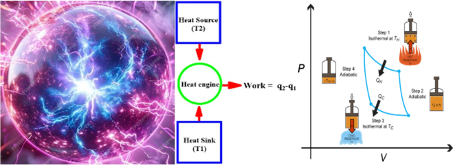
The Carnot cycle is an idealized thermodynamic cycle that defines the maximum possible efficiency for a heat engine operating between two temperature reservoirs
. In the MRC analogy:
1) The "hot reservoir" can be considered the state of the high magnetic energy density before reconnection. The local electromagnetic fields, which periodically turbulent magnetic reconnect in various scales (a cascade of plasma turbulence eddies) correspondently are heat source due to releasing magnetic energy at changing magnetic topology. The working body – plasma under external turbulence control (pumping – discharge or magnetic reconnections of inner local fields) as a heat engine at working cycle compression-expansion of plasma.
2) The "cold reservoir" is the state of the lower magnetic energy density after reconnection, along with the dissipated energy (heat, kinetic energy of outflows). Accordingly, the surroundings is a heat sink. Also, it included external direct energy converters and magnetic coils.
3) The α-dynamo phase acts as the "compression" (energy input) stage, building up the "hot reservoir." Energy is input into the plasma to drive turbulence and amplify the magnetic field. This increases the magnetic energy density of the system.
4) The magnetic reconnection phase acts as the "expansion" (energy output) stage, releasing the stored energy. Stored magnetic energy is released and converted into other forms (heat, kinetic energy, radiation). This decreases the "magnetic energy density" of the system.
Energy is exchanged between the "magnetic energy reservoirs" and the plasma/surrounding environment. This includes the heat that is generated from turbulent magnetic reconnections, plasma resistivity, and also the output of heat that is desired from the system. The Carnot efficiency is given by:
where
TC is the temperature of the cold reservoir (surrounding plasma environment) and
TH is the temperature of the hot reservoir ("magnetic energy reservoirs" that are sites of turbulent magnetic reconnections. In the MRC analogy, instead of traditional temperatures, we would need to define equivalent "magnetic energy temperatures" or "magnetic potential" values that represent the energy density of the magnetic fields at the different stages of the cycle and in different places of the spheromak, which is proportional of square of magnetic field strength
B2. In
| [30] | Yamada, M., Yoo, J., Jara-Almonte, J. et al. Conversion of magnetic energy in the magnetic reconnection layer of a laboratory plasma. Nat Commun. 5, 4774 (2014). 8 p. https://doi.org/10.1038/ncomms5774 |
[30]
and other references defining that experimentally observed ratios of magnetic field strength before magnetic reconnection and in diffusion region are (B
in/B
DR) ~ 10-20 or more. Correspondingly, theoretically efficiency of MRC limited very high values, order ~ (1 – 0.1
2 = 0.99).
Factors affecting MRC efficiency are resistive, turbulence, radiation, confinement losses, α-dynamo, turbulent magnetic reconnection and control system efficiency. For optimization of MRC duty cycle need correspondently minimize losses, maximize the efficiency of magnetic energy conversion during α-dynamo and reconnection, optimize the control system to reduce energy consumption, and maximize the temperature differential between the high and low magnetic energy states, in analogy to the Carnot cycle (for MRC duty cycle it possibly corresponds magnetic energy density). But direct analogy with thermodynamic Carnot cycle have limitation due:
1) Defining "Magnetic Temperatures": establishing a clear and measurable definition of "magnetic temperatures" or equivalent energy potentials is a significant challenge. Here we proposed using magnetic energy density as "Magnetic Temperatures", but possibly other helpful analogies.
2) Non-Equilibrium Processes: plasma processes like turbulence and reconnection are highly non-equilibrium, making it difficult to apply equilibrium thermodynamic concepts directly.
3) Complexity of Plasma Dynamics: the complex interplay of magnetic fields, plasma flows, and instabilities makes it challenging to create a simple and accurate thermodynamic model.
Figure 1, Appendix I, shows the analogy of the MRC duty cycle with the thermodynamic Carnot cycle, if we consider the pressure
p as the magnetic energy density
wME and the volume V as the state variable inverse to the turbulence rate.
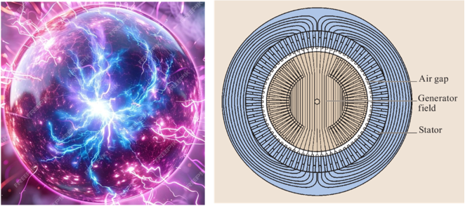
For the MRC direct energy converter applying external receiving coils, an analogy is with a rotating electrical machine. In this case:
Rotor Analogy: the plasma volume undergoing periodic compression and expansion can be likened to the rotating rotor. The changing magnetic field configuration and plasma β during these phases mimic the rotating magnetic field in a rotor.
Stator Analogy: the external receiving coils surrounding the plasma chamber are analogous to the stator in an electrical machine. They provide the confining magnetic field and interact with the changing plasma configuration to induce currents and potentially generate additional electrical power, as it shown on
Figure 2, Appendix I.
4. Mathematical Model of the MRC
Developing a complete and self-consistent mathematical model for a Magnetic Reconnection Converter (MRC) with instability-driven α-dynamo and triggered turbulent magnetic reconnection (TMR) is a highly complex task. This work is the continuation of paper
. It would involve a coupled system of partial differential equations from magnetohydrodynamics (MHD) or extended MHD, incorporating turbulence models, dynamo theory, and specific models for the chosen instabilities and reconnection triggering mechanisms. A conceptual outline of the key equations and terms that would be involved in such a model, highlighting the interconnectedness of the different physical processes, will be provided further on.
4.1. Basic MHD Equations as a System of Coupled Partial Differential Equations
4.1.1. Magnetic Field B and α-Dynamo Modeling
The evolution of the magnetic field B within the spheromak plasma for the turbulence pumping phase can be described by the resistive MHD induction equation, modified to include the α-dynamo effect (1). The term αB represents the generation of magnetic field due to the α-dynamo effect, that depends on the properties of the turbulence within the plasma, particularly its helicity H, and arises from the correlation between velocity and magnetic field fluctuations:
where denotes an average over turbulence, V′ and B′ are fluctuating velocity and magnetic field components, and α is the tensor, which depends on the properties of the turbulent flow (e.g., helicity). The specific form of the tensor α would depend on the nature of the turbulence driven by the chosen instability. For example, for drift-wave turbulence, α would be related to the gradients and magnetic field. Modeling the precise form and evolution of α is a complex aspect of dynamo theory, as it can be influenced by various plasma parameters and the magnetic field itself.
All properties of magnetic and electric fields in spheromak plasma are describing the Maxwell’s equations:
where in (
7) we assuming non-relativistic speeds and neglecting displacement current, and (
9) is the Ohm's Law, including resistivity
η and anomalous electric fields
Eanom arising from turbulence or kinetic effects.
4.1.2. Plasma Density Ρ
The evolution of the plasma density ρ is governed by the continuity equation, which expresses the conservation of mass:
where Sρ represents any sources or sinks of plasma within the system. For a closed system like the spheromak in the timescales of the MRC cycle, Sρ might be considered negligible, implying that the total number of particles remains approximately constant. However, in a more detailed model, factors like particle losses due to reconnection or the operation of an E×B cooling system might necessitate the inclusion of source or sink terms.
4.1.3. Momentum Equation (Newton’s Second Law)
(11)
where V is the plasma velocity, p is the plasma pressure, J is the current density, B is the magnetic field, ξ is the dynamic viscosity, and Fext represents external forces (e.g., from neutral beam injection).
4.1.4. Plasma Temperature T (Including Heating from Magnetic Reconnection) and Energy Equation
The evolution of the plasma temperature T (or more accurately, the internal energy density) can be described by the energy equation, which accounts for various heating and cooling processes:
(12)
Here, kB is the Boltzmann constant, q is the heat flux vector, p=ρkB T is the plasma pressure, ηJ2 represents Ohmic heating due to the electrical resistivity of the plasma, QMR represents the heating of the plasma due to the release of magnetic energy during turbulent magnetic reconnection, and Qoth accounts for other potential heating or cooling mechanisms such as radiation or the effect of an E×B cooling system. Modeling the term QMR is crucial for capturing the rapid temperature increase during the discharge phase. It might be phenomenologically represented as a source term proportional to the rate at which magnetic energy is being dissipated during reconnection, which in turn depends on the local magnetic field strength and the reconnection rate.
Another form of thermodynamics states may be presented as an energy balance:
(13)
where γ is the adiabatic index, E is the electric field, Q represents heating and cooling terms (e.g., Ohmic heating, radiation), and SE represents external energy sources (e.g., RF heating).
4.1.5. Magnetic Helicity H
The magnetic helicity
H=∫A⋅BdV, where
A is the magnetic vector potential
B=∇×A, is an important conserved quantity in ideal MHD. Its evolution in a resistive turbulent plasma is given by (
1):
(14)
The first term on the right-hand side represents the dissipation of magnetic helicity due to resistive effects. The second term involves the electric field E and can be related to the non-ideal terms in Ohm's law. The super-linear dependence on the Richardson number m > 1 and f(Г) represents the self-driven/self-sustained turbulence which generates the α-dynamo effect. In the context of the MRC, the α-dynamo effect is expected to contribute to the generation and increase of magnetic helicity during the charging phase, while turbulent magnetic reconnection might lead to a rapid change in the helicity distribution, even if the total helicity is approximately conserved.
In a turbulent plasma, the transport of momentum, heat, and magnetic field is significantly enhanced compared to laminar conditions. To accurately model the MRC, the standard MHD equations might need to be augmented to include the effects of turbulent transport. This can be done by introducing effective transport coefficients that account for the increased mixing and diffusion caused by the turbulent fluctuations. For example, the magnetic diffusivity η might be replaced by an effective turbulent diffusivity ηeff = η + ηT, where ηT is the contribution from turbulence. Similarly, turbulent viscosity and thermal conductivity might need to be included in the momentum and energy equations, respectively. Modeling these turbulent transport coefficients is a complex task and often relies on advanced turbulence closure models or empirical scaling laws derived from experimental observations or high-fidelity simulations. The evolution of magnetic helicity H in a plasma volume is governed by the helicity balance equation:
(15)
where: (dH/dt) is rate of change of magnetic helicity within the volume V, E is an electric field, B is a magnetic field, ψ is helicity flux function, ∂H/∂t|P is rate of change of helicity due to turbulent pumping. The increase in MF energy is related to the helicity injection rate through:
where μ₀ is the permeability of free space. The turbulent pumping term (∂H/∂t|P) can be modeled using mechanisms of Richardson's super-linear diffusion, self-generated / self-sustained turbulence, and drift- wave/interchange instability:
where D is the turbulent diffusion coefficient, which for Richardson's super-linear diffusion depends on the scale size of the turbulent eddies and can be expressed as D = D₀ (l/l₀)α with D₀ as the reference diffusion coefficient, l is the scale size of turbulent eddies, l₀ is reference scale size, and α is Super-linear diffusion exponent (typically α > 1). For mechanisms of self-generated/self-sustained turbulence and drift-wave/interchange instability, the turbulent diffusion coefficient D may take another form.
The mathematical model (
14)-(
17) describes the increase in magnetic field energy due to helicity injection under the influence of turbulent pumping. Key points of this system are:
1) The model captures the interplay between magnetic helicity, turbulent pumping, and super-linear diffusion in driving magnetic field amplification.
2) The turbulent diffusion coefficient D plays a crucial role in determining the efficiency of energy transfer from small-scale turbulence to large-scale magnetic fields, and generating α-dynamo through correlated motion of plasma parcels and their magnetic fields.
3) Solving this system of equations requires knowledge of the electric field E, the helicity flux function ψ, and the turbulent eddy scale size l, which may be obtained from experimental measurements or numerical simulations of the plasma.
This system of equations, along with appropriate boundary conditions and initial conditions, can be solved numerically to study the dynamics of magnetic field amplification in turbulent plasmas.
4.2. Incorporating Instabilities and Turbulent Magnetic Reconnection
To model the generation of turbulence by drift-wave or interchange instabilities in spheromak plasma, we would need to determine the conditions (based on plasma gradients, magnetic field geometry) under which these instabilities grow (using linear stability analysis). This would provide growth rates and mode structures. Since the α-dynamo relies on turbulent correlations, we would need to employ turbulence models. These could range from Reynolds-Averaged Navier-Stokes (RANS) approaches, introducing Reynolds stresses and turbulent fluxes, often requiring closure models (e.g., k−ϵ, mixing length models) that would need to be adapted for magnetized plasmas to Large Eddy Simulation (LES), resolving large-scale turbulent eddies and modeling the effects of small-scale eddies, and Direct Numerical Simulation (DNS), resolving all relevant scales of turbulence (computationally very expensive). The growth of the instabilities can lead to a saturated turbulent state that should be taken into account in this modelling.
Modeling magnetic reconnection requires going beyond ideal MHD, especially in the diffusion region where magnetic field lines break and reconnect. This typically involves resistive MHD, including a finite resistivity η in Ohm's Law, which allows for magnetic diffusion and reconnection. The reconnection rate depends on the magnitude and spatial profile of η. In some regimes, the Hall effect (decoupling of ion and electron motions) becomes important and can significantly affect the reconnection rate and dynamics. For a more accurate description of the diffusion region, kinetic plasma models (e.g., particle-in-cell simulations) might be necessary, especially when dealing with collisionless plasmas. The model would need to incorporate how external control (e.g., changes in boundary conditions, applied magnetic fields, plasma flows) can trigger the onset of rapid turbulence magnetic reconnection in many sites of spheromak plasma.
4.3. Discussion of Boundary Conditions Relevant to the Spheromak Configuration
To obtain physically meaningful solutions from the system of coupled partial differential equations described above, it is necessary to specify appropriate boundary conditions at the edge of the spheromak plasma. These boundary conditions will depend on the specific design of the MRC, including the nature of the confinement vessel and the presence of external components. For a spheromak confined by a conducting wall, the tangential component of the electric field at the wall is typically zero, which translates to conditions on the magnetic field components. For instance, the normal component of the magnetic field must be zero at the wall, and the tangential components must satisfy certain conditions related to induced currents in the conductor. Boundary conditions for the plasma velocity might include no-slip or free-slip conditions at the wall, depending on the assumed interaction between the plasma and the wall. Similarly, boundary conditions for the plasma density and temperature need to be specified, such as no particle flux or a fixed temperature at the wall. The presence of external coils used for power extraction will introduce additional boundary conditions related to the induced currents and magnetic fields they generate. If an E×B cooling system is implemented using electrodes, the potentials applied to these electrodes will also define boundary conditions for the electric field within the plasma.
4.4. Feedback Control Implementation
To model the feedback control loops, the system of equations would need to be coupled to representing how the plasma parameters are measured (Diagnostic Models), describing how the control inputs (e.g., gas injection rates, heating power, coil’s currents, etc.) affect the plasma (Actuator Models), and mathematical expressions defining how the actuators are adjusted based on the measured parameters and the desired setpoints for the MRC duty cycle. These control laws would likely involve the Proportional-Integral-Derivative (PID) controllers or more advanced algorithms as Physical Informed Neural Networks (PINN).
First, we consider the Instability Drive Control Loop and illustrate how its operation could be formulated mathematically within the context of the plasma model. Let's say the primary measured parameter for controlling drift wave instability is the density gradient scale length Lρ = −ρ/(∇ρ), where ρ is the plasma density. The diagnostic system provides a measurement of this quantity, Lρ,meas, which might have some associated error or delay Lρ,meas(t) = Lρ (r, t−τd)+ϵ(t) where r is the radial position, τd is the diagnostic delay, and ϵ(t) is the measurement noise. The actual Lρ(r, t) evolves according to the plasma transport equations (which are embedded within the MHD framework, specifically in the continuity equation and the terms affecting density profiles). The control system takes the measured density gradient scale length and compares it to a desired setpoint, Lρ,set. A common control law is PID controller: u(t)=Kpe(t)+Ki∫te(τ)dτ+Kd( de(t)/dt) where u(t) is the control output (e.g., the rate of gas injection), error of control e(t)= Lρ,set − Lρ,meas(t), and Kp, Ki, and Kd are the proportional, integral, and derivative gain constants, respectively. The control output u(t) then acts on the plasma through an actuator. In this case, the actuator is the gas injection system. The rate of change of the plasma density due to gas injection (Sρ in the continuity equation) would be a function of the control output Sρ(r, t)=f(u(t−τa)) where τa is the actuator delay, and f is a function describing how the gas injection rate affects the local plasma density. This function would depend on the specifics of the gas injection system and plasma transport processes. Further, the gas injection Sρ modifies the density profile in the continuity equation (10). Changes in the density profile affect the density gradient ∇ρ and thus the density gradient scale length Lρ, that is measured by the diagnostics, and the measured value is fed into the control law. The control law calculates the required gas injection rate to drive Lρ,meas(t) towards Lρ,set(t). The gas injection system acts on the plasma according to the actuator model, closing the feedback loop. Other control loops would have similar structures.
For α-dynamo Optimization Control Loop measured parameters are:
1) Magnetic field strength ⟨∣B∣⟩ (average or local strength of the generated magnetic field),
2) Magnetic field fluctuations ⟨∣δB∣2⟩ (amplitude of turbulent magnetic field fluctuations),
3) Cross-helicity ⟨(v′×B′)⋅⟨B⟩⟩ (a measure of the correlation between velocity and magnetic field fluctuations aligned with the mean field, directly related to the α- effect).
4) Magnetic Helicity Hm=∫A⋅BdV (a global quantity indicating the linkage and twist of the magnetic field lines), and outputs (actuators) used for:
1) Fine-tuning of instability drive parameters adjusting gas injection rates, heating power profiles, magnetic field shear, and flow drive parameters to modify the characteristics of the turbulence (amplitude, correlation times, spatial scales) and thus the α- effect.
2) Introduction of weak, tailored magnetic field perturbations through drift-waves or interchange instabilities that could potentially seed or enhance the α-dynamo action in specific regions.
The operation of this control loop should:
1) Maximize the growth rate of the magnetic field strength B due to the α-dynamo.
2) Enhance the generation of magnetic helicity H to sustain the α-dynamo process.
3) Optimize the spatial structure of the generated magnetic field for efficient energy storage and subsequent reconnection.
4) Potentially suppress parasitic instabilities that might hinder the dynamo action. The control law takes the measured magnetic field properties and adjusts the instability drive parameters δuinstab to optimize a performance metric JAD related to the α-dynamo efficiency:
δuinstab(t)=JAD(⟨∣B∣⟩,⟨∣δB∣2⟩,⟨(v′×B′)⋅⟨B⟩⟩,Hm,Ln,meas)(18)
This adjustment would then feed back into the MHD equations by modifying the source terms or transport coefficients that are influenced by the instability drive.
For Magnetic Reconnection Triggering Control Loop measured parameters are:
1) Local magnetic field topology (detection of regions with strong, anti-parallel magnetic field components, using magnetic probes or reconstruction techniques).
2) Current density ∣J∣ (high current densities in regions of anti-parallel fields can indicate a propensity for reconnection).
3) Plasma β (3) (which can influence reconnection rates).
4) Flow velocities v (monitoring plasma flows that can drive or impede reconnection).
Outputs of this control loop use for:
1) Rapid adjustment of external magnetic field coils creates or enhances magnetic field gradients and X-points where turbulent magnetic reconnections can occur.
2) Pulsed plasma flow injection (localized) drives plasma towards the reconnection site to thin current sheets.
3) Localized heating or current injection that reduces resistivity locally to enhance the reconnection rate.
Aims of this control loop are:
1) Initiate magnetic reconnection at a pre-determined time or when the stored magnetic energy (indicated by the magnetic field strength, stochasticity and volume) reaches a threshold.
2) Control the location and rate of reconnection to optimize energy release and direct it towards the energy extraction mechanisms.
3) Potentially trigger multiple reconnection events in a controlled manner. This control loop would monitor the conditions favorable for turbulent magnetic reconnections in many sites, and generate a trigger signal utrigger when certain criteria are met:
utrigger(t)=gMR(Blocal,∣J∣local,βlocal,vlocal,⟨∣B∣⟩global,t)(19)
This trigger signal would then activate the actuators (e.g., change coil currents Icoils(t)=Icoils,base+δI(utrigger) that directly modify the magnetic field configuration in Maxwell's equations.
For
Heating Power Control, the measured parameter might be plasma temperature or its gradient, the actuator would be the heating power, and the control law would adjust the power to maintain the desired temperature profile (affecting the energy equation (
12,
13).
For
Magnetic Field Shaping Control the measured parameter would be the magnetic field configuration (e.g., parameters of magnetic field, safety factor profile
q(r), etc.), the actuator would be the currents in external magnetic field coils, and the control law would adjust these currents to achieve the desired magnetic field topology (affecting equations (
1), (
6-17) (through boundary conditions).
For
Flow Control the measured parameter would be plasma flow velocity or shear, the actuator could be tangential neutral beam injection (NBI) or rotating magnetic fields, and the control law would adjust the power or frequency of these actuators (affecting the momentum equation (
11)).
In summary, the control system for an MRC based on a cyclic “α-dynamo - turbulent magnetic reconnections” process involves actively manipulating plasma parameters and magnetic fields at different stages of the cycle to:
1) Create and sustain the conditions for instability-driven α-dynamo.
2) Optimize the α-dynamo process for magnetic field amplification.
3) Trigger turbulent magnetic reconnections in many sites in a controlled manner.
4) Manage the energy release and prepare for the next cycle.
Each of these stages requires specific measurements, actuators, and control objectives that need to be coordinated for efficient and stable operation. The effective operation of an MRC requires a highly integrated control system that coordinates these different feedback loops. The transitions between the α-dynamo phase and the turbulent magnetic reconnections phase need to be carefully managed. For instance, the control system needs to know when the magnetic field has built up sufficiently to trigger reconnections and then needs to manage the post-reconnection plasma state to facilitate the restart of the α-dynamo phase. Advanced control techniques, such as model predictive control or machine learning, might be necessary to handle the complex, non-linear interactions within the plasma and optimize the overall energy conversion efficiency and stability of the MRC.
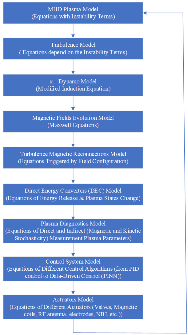
The complete mathematical model of MRC is a large system of coupled non-linear partial differential equations (MHD) along with ordinary differential equations (control laws) and algebraic equations (diagnostic and actuator models). Developing and solving such a model would require significant computational resources and a deep understanding of plasma physics, fluid dynamics, and electromagnetism. The outline above provides a conceptual framework of the key components and their interrelationships. Specific implementations would depend on the chosen instability, the desired operating regime of the MRC, and the level of detail required. Research in this area would involve a combination of theoretical modeling, numerical simulations, and experimental validation. As a prospective future direction, possible to apply the data-driven approach, based on physically informed neural network models (PINN)
| [47] | Lawal, Z. K.; Yassin, H.; Lai, D. T. C.; Che Idris, A. Physics-Informed Neural Network (PINN) Evolution and Beyond: A Systematic Literature Review and Bibliometric Analysis. Big Data Cogn. Comput. 2022, 6, 140. https://doi.org/10.3390/bdcc6040140 |
[47]
for MRC simulation and development.
Schematic representation of the coupled systems of equations of the MRC mathematical model shown in
Figure 3, Appendix II.
5. Conceptual Diagrams and Illustrations of MRC
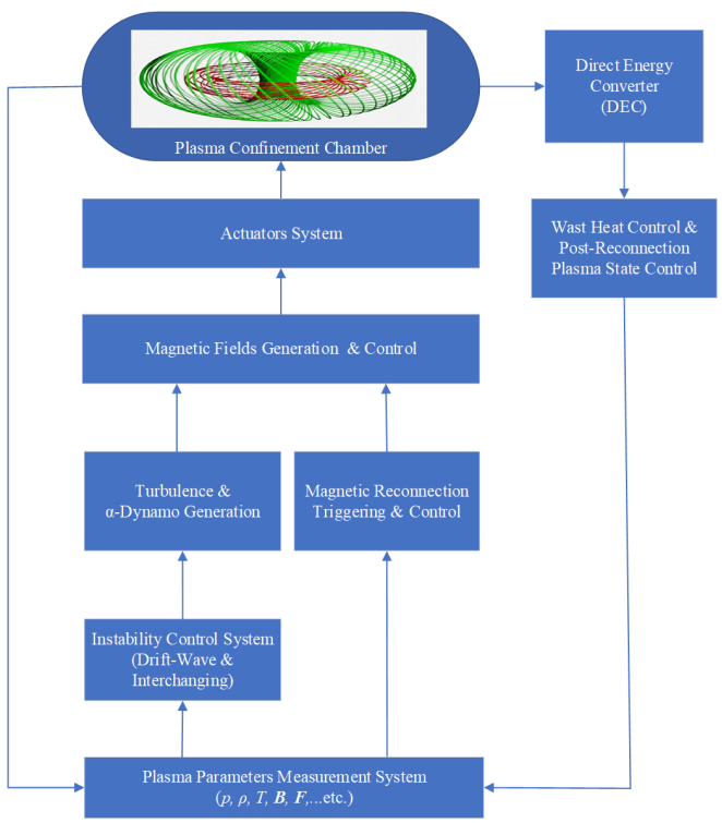
Principal Diagram of the Magnetic Reconnection Converter (MRC), shown on
Figure 4, Appendix III, included the next key components:
1) Plasma Confinement Chamber with the spheromak plasma: represented as a toroidal (doughnut-shaped) volume with internal magnetic field lines depicted.
2)
Plasma Parameter Measurement System, which collects sets of needed parameters (density
ρ, temperature
T, pressure
p, flows
F, magnetic fields
B, etc.) in different sites of the plasma confinement chamber, and also calculates magnetic and kinetic stochasticity of plasma
| [17] | Lazarian A., Eyink G. L., Jafari A., Kowal G., Li H., Xu S., Vishniac E. T. 3D turbulent reconnection: Theory, tests, and astrophysical implications, Phys. Plasmas 27, 012305 (2020). 63 p. https://doi.org/10.1063/1.5110603 |
[17]
. Various sensors and probes attached to or near the confinement chamber and connected with a central processing unit, such as: magnetic probes (measuring magnetic field
B strength and direction), Langmuir probes (measuring plasma density
ρ and temperature
T), Thomson scattering (measuring electron temperature
Te and density
ρe), interferometry (measuring plasma density
ρ), spectroscopy (measuring ion temperature
Ti and impurities), Doppler reflectometry (flow diagnostics).
3) Magnetic Fields Generation & Control System with sets of coils, electrodes, antennas surrounding the confinement chamber, connected to power supplies and control system. Main magnetic field coils generate the primary confining magnetic field. Control coils used to shape the magnetic field, control shear and induce or trigger reconnection. Power supplies are connected to the coils, with control signals as inputs. Arrows indicate adjustable current.
4) Instability Control System receives and analyzes signals from the plasma parameter measurement system. Implements the feedback loops to drive instabilities, optimize the α-dynamo (adjusting magnetic fields, heating, gas injection, flows). Sends control signals to the magnetic field control system, heating systems, gas injection system, and flow drive systems.
5) Turbulence & α-Dynamo Generation driven by controlled drift-wave and interchange instabilities, and is a subsystem of the Instability Control System.
6) Magnetic Reconnections Triggering & Control for magnetic fields and flows manipulation. A specific module within the overall control system or a dedicated subsystem of Magnetic Fields Generation & Control that analyzes magnetic field configurations and sends rapid control signals. Identifies conditions favorable for reconnection (e.g., anti-parallel fields, high current densities). Generates trigger signals for rapid changes in magnetic field configuration or plasma flows to initiate reconnection, and sends signals to specific control coils or flow actuators.
7) Actuator System as it was pointed early include heating subsystem (RF heating with antennas emitting radio waves, Neutral Beam Injection (NBI) injectors firing beams of neutral particles, Ohmic heating for current driven through the plasma); gas injection subsystem with fast valves and pipes injecting gas into the chamber; flow drive subsystem applying tangential neutral beams or rotating magnetic fields; magnetic fields generation & control system.
8)
Direct Energy Convertor (DEC) or Energy Release & Conversion System located around the confinement chamber and captures the released energy with next proposed components: divertor (collects exhaust plasma and heat), heat exchangers (convert thermal energy into electricity or other useful forms), electromagnetic induction coils (capture energy from changing magnetic fields or plasma currents), energetic particle collectors (electrodes of poloidal and tangential
E×B cooling
| [2] | Rax J.-M., Kolmes E.J. and Fisch N.J. Efficiency and Physical Limitations of Adiabatic Direct Energy Conversion in Axisymmetric Fields. PRX Energy 4, 013007 (2025), p. 15, https://doi.org/10.1103/PRXEnergy.4.013007 |
[2]
). While not a direct feedback loop controlling the reconnection process itself after it's triggered, this aspect involves managing the consequences of energy release for efficient extraction. For effective energy conversion in MRC necessary to measure the following parameters:
9) Plasma temperature and density in the outflow regions.
1) Energetic particle fluxes.
2) Heat flux to the chamber walls or divertors.
3) Electrical currents induced by plasma motion.
This would involve modeling the energy transport and conversion processes after reconnection, influenced by the magnetic field configuration and plasma properties resulting from the event. Control actions would be based on maintaining safe operating limits and optimizing energy extraction efficiency, feeding back to the overall plasma parameters and potentially influencing the subsequent α-dynamo phase. For example, excessive or insufficient heat loads might trigger adjustments in the reconnection rate or frequency of the cycle.
Main MRC control feedback loops for plasma parameters, shown on
Figure 4, Appendix III (additionally to theoretical explain in Section 4) are:
1) Instability Drive Control Loop:
Inputs of this control loop are plasma density gradients ∇ρ, temperature gradients ∇T, magnetic field shear s=(r/q)dq/dr for drift waves, pressure gradients relative to magnetic field curvature ∇p⋅B×∇B for interchange instabilities, plasma flow shear (∂V/∂r). Outputs can drive the next actuators: 1) gas injection rate for controls plasma density and its gradient, 2) heating power (e.g., RF, Neutral Beam Injection) for controls plasma temperature and its gradient, 3) external magnetic field coils for adjust the magnetic field configuration to control shear and curvature, 4) plasma flow drive (e.g., tangential neutral beam injection, rotating magnetic fields) that induces and controls plasma flows and flow shear.
This control loop must maintain plasma parameters within the unstable regime for the desired instability, optimizing its growth rate and the resulting turbulence characteristics (e.g., frequency spectrum, wave number), and maximize the conditions favorable for the α-dynamo (coherent magnetic stochasticity).
2) α-Dynamo Optimization Loop:
Inputs of this control loop are magnetic field strength B, magnetic field fluctuations δB, correlation between velocity and magnetic field fluctuations ⟨v′×B′⟩, indicators of magnetic helicity H, such as curvature, bending or other topological characteristics. Outputs can drive the next actuators for control parameters of instability drive loop through: 1) fine-tuning gas injection, 2) heating power, 3) magnetic field configuration, and 4) flow drive to influence the turbulence characteristics and helicity generation. Potentially, a possible application of weak, specific magnetic field perturbations that could seed or guide the dynamo action.
The control loop must maximize the growth rate and saturation level of the generated magnetic field through the α-dynamo, monitoring the development of magnetic complexity and stored energy.
3) Magnetic Reconnection Triggering Loop:
As inputs uses magnetic field topology (identification of regions with antiparallel fields), current density J, local plasma pressure p, and flow velocities V. Outputs influenced for adjustment of external magnetic field coils that force magnetic field lines with opposite directions together, pulsed plasma flow injection drive plasma towards regions of antiparallel fields and triggering reconnection, localized heating or current injection locally reduce plasma resistivity, facilitating reconnection.
This feedback control loop initiates magnetic reconnection at a controlled time and locations when the stored magnetic energy is sufficient for efficient and rapid energy release.
4) Direct Energy Converter (DEC):
In addition to ways, considering in
here we more detailed defining external receiving coils and
E×B cooling
| [2] | Rax J.-M., Kolmes E.J. and Fisch N.J. Efficiency and Physical Limitations of Adiabatic Direct Energy Conversion in Axisymmetric Fields. PRX Energy 4, 013007 (2025), p. 15, https://doi.org/10.1103/PRXEnergy.4.013007 |
[2]
.
The direct conversion of energy from the MRC with external receiving coils apply the principle of electromagnetic induction, described by Faraday's law. During the turbulent discharge phase, the rapid changes in the magnetic field within the spheromak, caused by the magnetic reconnection events and the associated changes in plasma currents, will induce an electromotive force (EMF) in the external coils placed around the plasma. Faraday's law states that the induced EMF in any closed circuit is equal to the negative of the time rate of change of the magnetic flux through the circuit: E=−dΦB/dt, where ΦB=∫B⋅dA is the magnetic flux. The changing magnetic flux produced by the plasma currents will thus induce a voltage in the external coils, which can then drive an electrical current through a load, resulting in the generation of electrical power. The efficiency of this power conversion process depends on the strength and rate of change of the magnetic field, the geometry and number of turns of the external coils, and the magnetic coupling between the plasma and the coils. Several factors need to be considered in the design of the external coils to maximize the efficiency of power extraction from the MRC. The number of turns in each coil is directly proportional to the induced EMF for a given rate of change of magnetic flux. Therefore, increasing the number of turns can enhance the output voltage. The geometry of the coils, including their shape and size, and their placement relative to the spheromak plasma, will significantly affect the amount of magnetic flux that links the coils. Coils placed closer to the plasma and oriented to maximize the interception of the changing magnetic field lines will generally exhibit a stronger induced EMF. The frequency spectrum of the changing magnetic fields produced by the turbulent reconnection events will also influence the optimal design of the coils. For instance, if the reconnection events occur rapidly, the coils and the associated electrical circuitry need to be designed to handle high-frequency signals. Consideration of the magnetic field structure of the spheromak and the expected locations and patterns of magnetic reconnection will be crucial for strategically positioning the coils to capture the maximum amount of energy. Estimating the potential power output from the MRC requires a detailed understanding of the amount of magnetic energy stored in the spheromak during the charging phase and the fraction of this energy that is released and converted into changing magnetic flux during the turbulent reconnection phase. This would ideally be determined through numerical simulations based on the mathematical model described earlier. However, order-of-magnitude estimates can be made based on typical magnetic field strengths and plasma volumes achieved in spheromak experiments, along with estimates of the reconnection rate from turbulent reconnection theory. The power output will also depend on the efficiency of the magnetic flux coupling between the plasma and the external coils, as well as the efficiency of the electrical circuit connected to the coils. A more precise estimation would require solving the coupled MHD equations with the alpha dynamo term and modeling the interaction with the external coils.
E×B cooling mechanism (drift) is a fundamental phenomenon in plasma physics that describes the motion of charged particles in the presence of both electric
E and magnetic
B fields
| [2] | Rax J.-M., Kolmes E.J. and Fisch N.J. Efficiency and Physical Limitations of Adiabatic Direct Energy Conversion in Axisymmetric Fields. PRX Energy 4, 013007 (2025), p. 15, https://doi.org/10.1103/PRXEnergy.4.013007 |
[2]
. The drift velocity
vE×B= (E×B)/B2, and it is perpendicular to both the electric and magnetic field vectors. This drift is independent of the charge and mass of the particle. By carefully configuring electric fields within the spheromak plasma, it is possible to selectively transport charged particles based on their energy. For instance, if an electric field is applied such that the resulting
E×B drift directs high-energy particles towards the edge of the plasma, where they can be removed, this can lead to a net cooling of the plasma. This selective removal of energetic particles can be an effective way to reduce the plasma temperature and kinetic stochasticity after the discharge phase of the MRC cycle, preparing the plasma for the next charging phase. Implementing
E×B cooling in the MRC based on a spheromak configuration can be achieved through various arrangements of external electrodes or coils. Given the spheromak's characteristic poloidal and toroidal magnetic field components, an electric field applied in either of these directions can induce an
E×B drift. For example, poloidal electrodes placed at different electric potentials could create a radial electric field. This radial electric field, in conjunction with the toroidal component of the spheromak's magnetic field, would result in an axial
E×B drift, potentially directing particles along the axis of symmetry. Conversely, toroidal electrodes could create an axial electric field, which, when combined with the poloidal magnetic field, would lead to a radial
E×B drift, potentially moving particles towards or away from the center of the spheromak. Another possibility involves using specially designed external coils to induce localized electric fields within the plasma. These induced electric fields, interacting with the main spheromak magnetic field, could then be used to achieve the desired
E×B drift for cooling. The optimal configuration would likely depend on the specific magnetic field structure of the spheromak and the desired direction of particle transport for effective cooling. The
E×B cooling mechanism would ideally be implemented after the turbulent discharge phase of the MRC cycle. Following the rapid heating of the plasma due to magnetic reconnection, a period of active cooling would be beneficial to reduce the plasma temperature and kinetic energy before the next turbulent pumping phase begins. By selectively removing the most energetic particles,
E×B cooling can help to quickly reset the plasma to a state more conducive to the α-dynamo effect. Efficient cooling can also contribute to maintaining the overall stability of the spheromak plasma and potentially allow for a higher repetition rate of the MRC cycle, leading to a more continuous and efficient energy conversion process. The integration of
E×B cooling would require careful control of the applied electric and magnetic fields to ensure that only the desired cooling effect is achieved without disrupting the confinement of the bulk plasma or interfering with the power extraction process.
5) Post-Reconnection Plasma State Control Loop:
As inputs uses plasma temperature T, density ρ, pressure p, flow velocities v after the reconnection events, and residual magnetic field strength and configuration Br. Outputs influenced for adjustment of gas puffing/exhaust that control plasma density and remove reaction products, heating/cooling systems for manage plasma temperature, magnetic field configuration adjustment that prepare the plasma for the next cycle of instability growth and dynamo action, flow control that damp turbulent flows or re-establish conditions favorable for the chosen instability.
The aim of this loop is quench the reconnection process and prepare the plasma for the next cycle of instability-driven α-dynamo. This might involve reducing turbulence levels or re-establishing the necessary gradients for instability growth.
All these systems are interconnected in the following way: The plasma is confined and manipulated by the magnetic field generation and control system and influenced by the actuator systems. The plasma parameter measurement system constantly monitors the state of the plasma. This data is fed into the instability and α-dynamo control system, which adjusts the actuator systems to drive instabilities and optimize the α-dynamo, leading to an amplified and complex magnetic field. The magnetic reconnection triggering system monitors the magnetic field and plasma conditions. When the conditions are right, it signals the magnetic field control system and flow drive systems to trigger turbulent magnetic reconnection. Magnetic reconnection releases energy in the form of plasma heating, energetic particles, and outflows. The energy release and conversion system captures this energy and converts it into a useful form. The post-reconnection state is monitored by the plasma parameter measurement system, and the control system adjusts the actuators to prepare for the next cycle of instability growth and dynamo action.
6. Discussion and Challenges
6.1. Analysis of the Feasibility and Potential Advantages of the Proposed MRC
The feasibility of the proposed MRC hinges on several key aspects. The ability to reliably generate and control helical turbulence within a spheromak plasma to drive an efficient α-dynamo effect is crucial for the energy storage phase. Achieving a sufficient level of magnetic field stochasticity that can consistently trigger widespread turbulent magnetic reconnection at the desired point in the cycle is another critical requirement. Furthermore, the efficient extraction of the released energy using external coils and the effective implementation of an E×B cooling mechanism are essential for the overall performance of the device. If these challenges can be overcome, the MRC offers several potential advantages. Direct energy conversion from the plasma to electricity could lead to higher efficiencies compared to traditional thermal cycles. The compact nature of the spheromak configuration might result in a smaller and potentially more cost-effective MRC energy system. The cyclic and potentially pulsed nature of the power output could also be advantageous for specific applications and grid integration.
6.2. Identification of Key Challenges
Implementing the MRC concept presents several significant challenges. The crucial question is whether the energy output from the magnetic reconnection stage can be greater than the energy input required to drive the α-dynamo and sustain the system. If the energy losses in each stage (e.g., resistive losses in the plasma, energy radiated away) are too high, the cycle would not be self-sustaining or produce net positive energy. The timescales for magnetic reconnection and alpha-dynamo action might be very different. Reconnection can be relatively fast, while the large-scale amplification of magnetic fields by an alpha-dynamo can take longer, depending on the system's size and plasma parameters. Coordinating these different timescales in a cyclical process would be complex. Precisely controlling the generation and characteristics (especially helicity) of turbulence within a high-temperature plasma is a complex task. Triggering turbulent magnetic reconnection reliably and at the optimal time in the cycle requires a deep understanding of the conditions leading to its onset and potentially the development of active control methods. Achieving high efficiency in the direct conversion of the rapidly changing magnetic energy to electrical energy using external coils will depend on optimizing the coil design and their coupling to the plasma, which might be affected by the turbulent nature of the discharge. Implementing an effective E×B cooling system without disrupting the plasma confinement or the overall cycle dynamics could also be technically challenging. Finally, maintaining the overall stability of the spheromak plasma throughout the turbulent pumping and discharge phases is paramount for the reliable operation of the MRC. From a thermodynamic perspective, any energy conversion process increases entropy. Maintaining a highly ordered state like a strong magnetic field through turbulence and then releasing it through reconnection requires careful management of entropy.
6.3. Comparison with Existing Fusion and Energy Conversion Technologies
Compared to mainstream fusion research focused on tokamaks and stellarators, the MRC based on a spheromak represents a more compact and potentially simpler approach. However, spheromak research is generally at an earlier stage of development, and achieving the high temperatures and densities required for sustained fusion reactions has been a significant challenge. While the MRC concept focuses on magnetic energy conversion rather than direct fusion power extraction, the underlying plasma physics and confinement principles are related. Compared to other advanced energy conversion technologies, such as MHD generators, the MRC utilizes a fundamentally different approach based on the cyclic storage and release of magnetic energy through the α-dynamo and turbulent reconnection. The potential efficiency and scalability of the MRC need to be thoroughly evaluated against these existing and emerging technologies through further research and development.
7. Conclusion
7.1. Summary of the Proposed MRC Concept and Its Potential
The proposed Magnetic Reconnection Converter (MRC) presents a novel and potentially transformative approach to energy conversion. By leveraging the α-dynamo effect for magnetic energy storage within a spheromak plasma and subsequently releasing this energy through controlled turbulent magnetic reconnection, the MRC aims for a direct pathway to electrical power generation. This cyclic process, characterized by distinct charging and discharging phases and potentially enhanced by E×B cooling, offers the promise of a compact and efficient energy conversion device. The inherent properties of the spheromak configuration, coupled with the dynamic interplay of turbulence, magnetic field generation, and reconnection, form the foundation of this innovative concept. As a hypothesis, it can also be assumed that the thermodynamic cycle "α-dynamo-turbulent magnetic reconnection" is an additional source of energy for stars, along with the thermonuclear fusion reaction, if the α-dynamo is generated not by fusion energy, but for example, the gravity of stars.
7.2. Recommendations for Future Research and Development
Realizing the potential of the MRC will require significant future research and development efforts. Detailed numerical simulations are essential to model the complex interplay of the α-dynamo effect and turbulent magnetic reconnection within a spheromak, allowing for the optimization of operating parameters and the prediction of energy conversion efficiencies. Experimental studies are needed to validate the theoretical predictions, focusing on the generation and control of helical turbulence in spheromak plasmas and the triggering and characterization of turbulent magnetic reconnection events. Furthermore, research into the design and optimization of external coils for efficient power extraction and the development of effective E×B cooling techniques are crucial for the practical implementation of the MRC. Continued theoretical work is also necessary to refine the mathematical models of turbulent plasma phenomena and to better understand the fundamental physics governing the proposed energy conversion cycle.
Abbreviations
MRC | Magnetic Reconnection Converter |
MF | Magnetic Field |
TMR | Turbulent Magnetic Reconnection |
CS | Current Sheets |
DR | Diffusion Region |
MHD | Magneto Hydro Dynamic |
CHTMR | Counter-Helicity TMR |
SPH | SPHeromak |
NBI | Neutral Beam Injection |
RF | Radio Frequency |
Author Contributions
Oleg Agamalov is the sole author. The author read and approved the final manuscript.
Funding
This work is not supported by any external funding.
Data Availability Statement
The data supporting the outcome of this research work has been reported in this manuscript and Appendixes.
Conflicts of Interest
The author declares no conflicts of interest.
Appendix
Appendix I: The Analogy of the MRC Duty Cycle with the Thermodynamic Carnot Cycle and a Rotating Electrical Machine
Figure 1. The analogy of the MRC duty cycle with the thermodynamic Carnot cycle.
Step 1. Quasi-isothermal expansion: heat, QH, is absorbed from the hot reservoir at temperature TH (TMR at multi-scales). The heat goes into pushing the piston up (direct energy converter) as the gas (plasma) expands.
Step 2. Quasi-adiabatic expansion: the heat sources are removed (multi-scale TMR finished), and allow the gas (plasma) to expand adiabatically with no heat added to the system, and the temperature of the gas (plasma) drops to the temperature of the cold reservoir, TC (the surroundings plasmas).
Step 3. Quasi--isothermal compression: turbulence do work on the gas (plasma) to compress it at the same (about constant) the temperature. Instead, the heat, QC is transferred to the cold reservoir (the surroundings plasmas).
Step 4. Quasi-adiabatic compression: turbulence do work on the gas (plasma), but no longer allow the heat to be transferred to the cold reservoir (the surroundings plasmas) as for start of TMR need to rise back to TH.
Figure 2. The analogy of the MRC direct energy converter (DEC) with a rotating electrical machine.
Rotor Analogy: The plasma volume undergoing periodic compression and expansion can be likened to the rotating rotor. The changing magnetic field configuration and plasma β during these phases mimic the rotating magnetic field in a rotor. Stator Analogy: The external receiving coils surrounding the plasma chamber are analogous to the stator in an electrical machine. They provide the confining magnetic field and interact with the changing plasma configuration to induce currents and potentially generate additional electrical power.
Appendix II: The Coupled Equations Systems of the Magnetic Reconnection Converter (MRC) Mathematical Model
Figure 3. Schematic Representation of the Coupled Equations Systems of the Magnetic Reconnection Converter (MRC) Mathematical Model.
Appendix III: Principal Diagram of the Magnetic Reconnection Converter (MRC)
Figure 4. Principal Diagram of the Magnetic Reconnection Converter (MRC).
Appendix IV: Key Plasma Parameters and Their Evolution During the MRC Cycle
Table 1. Key Plasma Parameters and Their Evolution During the MRC Cycle.
Parameter | Charging Phase (α-dynamo effect through Turbulent Pumping) | Discharging Phase (Turbulent Magnetic Reconnection) | Cooling Phase (If Applicable) |
Plasma Beta (β) | Decreases to minimum | Increases to maximum | Remains high or decreases |
Magnetic Energy Density | Increases | Decreases rapidly | Remains lower |
Kinetic Energy Density | May slightly decrease or remain low | Increases significantly | Decreases |
Thermal Energy Density | May slightly decrease or remain low | Increases significantly | Decreases |
Magnetic Field Stochasticity | Increases to maximum | Decreases | Remains lower |
Global Helicity | Increases | May decrease or redistribute | Remains lower |
Plasma Temperature | May slightly decrease or remain low | Increases significantly | Decreases |
Appendix V: Comparison of MRC with Existing Technologies
Table 2. Comparison of MRC with Existing Technologies.
Technology | Energy Source | Confinement Method | Energy Conversion Method | Potential Advantages | Potential Challenges | Stage of Development |
Tokamak | Fusion (D-T) | Magnetic | Thermal to Mechanical to Electrical | Advanced stage, high confinement potential | Complex design, pulsed operation, high capital cost | Mature Research |
Stellarator | Fusion (D-T) | Magnetic | Thermal to Mechanical to Electrical | Inherently steady-state, potentially more stable | Complex magnetic coil design, challenging to optimize | Mature Research |
Fission Reactor | Nuclear Fission | N/A | Thermal to Mechanical to Electrical | Mature technology, high power output | Nuclear waste, safety concerns, fuel availability | Mature Commercial |
Solar PV | Sunlight | N/A | Direct conversion (photovoltaic effect) | Clean, renewable, distributed generation | Intermittent, weather-dependent | Mature Commercial |
MRC (Conceptual) | Plasma (Magnetic) | Magnetic (Spheromak) | Direct conversion (electromagnetic induction, E×B cooling) | Potentially compact, direct energy conversion, high energy density | Controlling turbulence, triggering reconnection, efficient cooling | Conceptual/ Early Research |
References
| [1] |
Agamalov O. General Concept of the Magnetic Reconnection Converter (MRC). Int J Energy Power Eng. 2024; 13(6): 108-134.
https://doi.org/10.11648/j.ijepe.20241306.11
|
| [2] |
Rax J.-M., Kolmes E.J. and Fisch N.J. Efficiency and Physical Limitations of Adiabatic Direct Energy Conversion in Axisymmetric Fields. PRX Energy 4, 013007 (2025), p. 15,
https://doi.org/10.1103/PRXEnergy.4.013007
|
| [3] |
Takeno H. et al. A Study of Miniaturization of Traveling Wave Direct Energy Converter for Loading on a Spacecraft, TRANSACTIONS OF THE JAPAN SOCIETY FOR AERONAUTICAL AND SPACE SCIENCES, AEROSPACE TECHNOLOGY JAPAN, 2016, Volume 14, Issue ists30, Pages. Pb_105-Pb_109, Released on J-STAGE September 30, 2016.
https://doi.org/10.2322/tastj.14.Pb_105
|
| [4] |
Takeno H. et al., Deceleration in a traveling wave direct energy converter for advanced fusion, Fusion Eng. Des. 83 (2008) 1696–1699.
https://doi.org/10.1016/j.fusengdes.2008.06.046
|
| [5] |
Tarditi A. et al. “Progress Towards the Development of a Traveling Wave Direct Energy Converter for Aneutronic Fusion Propulsion Applications.” (2015). 9 p.
https://doi.org/10.2514/6.2015-3861
|
| [6] |
Takeno H. et al. Recent Advancement of Research on Plasma Direct Energy Conversion, Plasma and Fusion Research, 2019, Volume 14, Pages 2405013, Released on J-STAGE February 22, 2019. 7 p.
https://doi.org/10.1585/pfr.14.2405013
|
| [7] |
Brown M., Gelber K., Mebratu M. Taylor state merging at SSX: experiment and simulation, [physics.plasm-ph] 28 Oct 2019. 17 p.
https://doi.org/10.48550/arXiv.1910.13861
|
| [8] |
Brown M. et al. (2009). "3D Reconnection And Flow Dynamics In The SSX Experiment". Current Trends In International Fusion Research: Proceedings of the 7th Symposium. Volume 1154, 167-176.
https://doi.org/10.1063/1.3204572
|
| [9] |
Brown M., Kaur M. (2019). "Magnetothermodynamics In SSX: Measuring The Equations Of State Of A Compressible Magnetized Plasma". Fusion Science And Technology. Volume 75, Issue 4. 275-282.
https://doi.org/10.1080/15361055.2019.1579622
|
| [10] |
Brown M., Schaffner D. (2015). "SSX MHD Plasma Wind Tunnel". Journal Of Plasma Physics. Volume 81, Issue 3.
https://doi.org/10.1017/S0022377815000227
|
| [11] |
Kornak T. W. Magnetic Reconnection Studies on SSX, 1998. 56 p.
https://plasma.physics.swarthmore.edu/SSX/publications/reconnection.pdf
|
| [12] |
Hubbard A., Del Sordo F., Kapyla P. J., Brandenburg A. The α effect with imposed and dynamo-generated magnetic fields. Monthly Notices of the Royal Astronomical Society, Volume 398, Issue 4, October 2009, Pages 1891–1899,
https://doi.org/10.1111/j.1365-2966.2009.15108.x
|
| [13] |
Tzeferacos, P., Rigby, A., Bott, A. et al. Laboratory evidence of dynamo amplification of magnetic fields in a turbulent plasma. Nat Commun 9, 591 (2018).
https://doi.org/10.1038/s41467-018-02953-2
|
| [14] |
Mizerski K. A, Yokoi N, Brandenburg A. Cross-helicity effect on α-type dynamo in non-equilibrium turbulence. Journal of Plasma Physics. 2023; 89(4): 905890412.
https://doi.org/10.1017/S0022377823000545
|
| [15] |
Tobias SM. The turbulent dynamo. Journal of Fluid Mechanics. 2021; 912: P1.
https://doi.org/10.1017/jfm.2020.1055
|
| [16] |
Yokoi N. (2013) Cross helicity and related dynamo, Geophysical & Astrophysical Fluid Dynamics, 107: 1-2, 114-184,
https://doi.org/10.1080/03091929.2012.754022
|
| [17] |
Lazarian A., Eyink G. L., Jafari A., Kowal G., Li H., Xu S., Vishniac E. T. 3D turbulent reconnection: Theory, tests, and astrophysical implications, Phys. Plasmas 27, 012305 (2020). 63 p.
https://doi.org/10.1063/1.5110603
|
| [18] |
Zhang J., Xu S., Lazarian A., Kowal G. Particle acceleration in self-driven turbulent reconnection, Journal of High Energy Astrophysics 40 (2023). 10 p.
https://doi.org/10.1016/j.jheap.2023.08.001
|
| [19] |
Beg R., Russell A., Hornig G. Evolution, Structure, and Topology of Self-generated Turbulent Reconnection Layers. The Astrophysical Journal, 940: 94 (32pp), 2022 November 20.
https://doi.org/10.3847/1538-4357/ac8eb6
|
| [20] |
Oishi J., Mac Low M., Collins D., Tamura M. Self-generated Turbulence in Magnetic Reconnection. The Astrophysical Journal Letters, 806: L12 (5pp), 2015 June 10.
http://dx.doi.org/10.1088/2041-8205/806/1/L12
|
| [21] |
Stroth U., Ramisch M. Towards turbulence control in magnetised plasmas. C. R. Physique 7 (2006) 686–691.
http://dx.doi.org/10.1016/j.crhy.2006.06.010
|
| [22] |
Pontin D. I., Priest E. R. Magnetic reconnection: MHD theory and modelling, Springer, 2022. 202 p.
https://doi.org/10.1007/s41116-022-00032-9
|
| [23] |
Scheeler M., van Rees W., Kedia H., Kleckner D., Irvine W. Complete measurement of helicity and its dynamics in vortex tubes, Science, 357 (6350), 2017. 4 p.
https://www.science.org/doi/10.1126/science.aam6897
|
| [24] |
Parker E. N. Magnetic reconnection and the lowest energy state, Earth Planets Space, 53, 2001. pp. 411–415,
https://earth-planets-space.springeropen.com/articles/10.1186/BF03353250
|
| [25] |
Yamada M., Kulsrud R., Ji H. Magnetic Reconnection, PPPL-4457. Information Services Princeton Plasma Physics Laboratory, 2009. 63 p.
https://www.osti.gov/biblio/965275
|
| [26] |
Pontin D. I., Horning G. The Parker problem: existence of smooth force-free fields and coronal heating, Springer, 2020. 54 p.
https://doi.org/10.1007/s41116-020-00026-5
|
| [27] |
Ji H., Daughton W., Jara-Almonte J., Le A., Stanier A., Yoo J. Magnetic reconnection in the era of exascale computing and multiscale experiments, [physics. plasm-ph] 18 Feb 2022. 35 p.
https://arxiv.org/abs/2202.09004
|
| [28] |
Jafari A., Vishniac E. Introduction to Magnetic Reconnection, [astro-ph. HE] 15 Jun 2018. 32 p.
https://doi.org/10.48550/arXiv.1805.01347
|
| [29] |
Yamada, M. Review of the recent controlled experiments for study of local reconnection physics. Earth Planet Sp 53, 509–519 (2001). 12 p.
https://doi.org/10.1186/BF03353263
|
| [30] |
Yamada, M., Yoo, J., Jara-Almonte, J. et al. Conversion of magnetic energy in the magnetic reconnection layer of a laboratory plasma. Nat Commun. 5, 4774 (2014). 8 p.
https://doi.org/10.1038/ncomms5774
|
| [31] |
Yamada, M., Chen, LJ., Yoo, J. et al. The two-fluid dynamics and energetics of the asymmetric magnetic reconnection in laboratory and space plasmas. Nat Commun 9, 5223 (2018). 11 p.
https://doi.org/10.1038/s41467-018-07680-2
|
| [32] |
Dahlin J. T., Drake J. F., Swisdak M. Electron acceleration in three-dimensional magnetic reconnection with a guide field, Phys. Plasmas 22, 100704 (2015). 6 p.
https://doi.org/10.1063/1.4933212
|
| [33] |
Dahlin J. T. Prospectus on electron acceleration via magnetic reconnection, Phys. Plasmas 27, 100601 (2020). 13 p.
https://doi.org/10.1063/5.0019338
|
| [34] |
Chien A. et al. Direct measurement of non-thermal electron acceleration from magnetically driven reconnection in a laboratory plasma, [physics. plasm-ph] 25 Jan 2022. 13 p.
https://doi.org/10.48550/arXiv.2201.10052
|
| [35] |
Oka M. et al. Particle Acceleration by Magnetic Reconnection in Geospace, Space Science Reviews (2023) 219: 75. 36 p.
https://doi.org/10.1007/s11214-023-01011-8
|
| [36] |
Eyink G., Aluie H. The breakdown of Alfven’s theorem in ideal plasma flows: Necessary conditions and physical conjectures. Physica D 223 (2006) 82–92 p.
https://doi.org/10.1016/j.physd.2006.08.009
|
| [37] |
Eyink, G., Vishniac, E., Lalescu, C. et al. Flux-freezing breakdown in high-conductivity magnetohydrodynamic turbulence. Nature 497, 466–469 (2013).
https://doi.org/10.1038/nature12128
|
| [38] |
Jafari A., Vishniac E. Topology and stochasticity of turbulent magnetic fields. Phys Rev E. 2019 Jul; 100 (1-1): 013201.
https://doi.org/10.1103/PhysRevE.100.013201
|
| [39] |
Jafari A., Vishniac E., Vaikundaraman V. Magnetic stochasticity and diffusion, [astro-ph. HE] 20 Aug 2019. 8p. doi:
https://doi.org/10.1103/PhysRevE.100.043205
|
| [40] |
Jafari A., Vishniac E., Vaikundaraman V. Statistical Analysis of Stochastic Magnetic Fields, [astro-ph. HE] 14 Jan 2020. 17 p.
https://doi.org/10.1103/PhysRevE.101.022122
|
| [41] |
Jafari A., Vishniac E. Power and spatial complexity in stochastic reconnection, [astro-ph. HE] 10 Apr 2020. 6 p.
https://doi.org/10.1063/5.0009150
|
| [42] |
Jafari, A. and Vishniac, E. Magnetic topology in fluids, 2019. 10 p.
https://doi.org/10.48550/arXiv.1909.07325
|
| [43] |
Jafari A., Vishniac E. Topological theory of physical fields, [astro-ph. HE] 8 Jan 2021. 13 p.
https://doi.org/10.48550/arXiv.1909.04836
|
| [44] |
Jafari A., Vishniac E., Xu S. Nanoflare Theory Revisited. The Astrophysical Journal, 906: 109 (10pp), 2021 January 10.
https://doi.org/10.3847/1538-4357/abca47
|
| [45] |
Jafari A. Does Magnetic Reconnection Change Topology? [physics. plasm-ph] 30 Aug 2024. 10 p.
https://doi.org/10.48550/arXiv.2408.13732
|
| [46] |
Ong C., Quek S. The most efficient thermodynamic cycle under general engine constraints. Am. J. Phys. 93, 144–149 (2025)
https://doi.org/10.1119/5.0199979
|
| [47] |
Lawal, Z. K.; Yassin, H.; Lai, D. T. C.; Che Idris, A. Physics-Informed Neural Network (PINN) Evolution and Beyond: A Systematic Literature Review and Bibliometric Analysis. Big Data Cogn. Comput. 2022, 6, 140.
https://doi.org/10.3390/bdcc6040140
|
Cite This Article
-
APA Style
Agamalov, O. (2025). Single-Volume Magnetic Reconnection Converter (MRC) with Variable β of Plasma Based on Thermodynamic Duty Cycle “α- Dynamo – Magnetic Reconnection”. International Journal of Energy and Power Engineering, 14(1), 29-49. https://doi.org/10.11648/j.ijepe.20251402.12
 Copy
|
Copy
|
 Download
ACS Style
Agamalov, O. Single-Volume Magnetic Reconnection Converter (MRC) with Variable β of Plasma Based on Thermodynamic Duty Cycle “α- Dynamo – Magnetic Reconnection”. Int. J. Energy Power Eng. 2025, 14(1), 29-49. doi: 10.11648/j.ijepe.20251402.12
Copy
|
Download
AMA Style
Agamalov O. Single-Volume Magnetic Reconnection Converter (MRC) with Variable β of Plasma Based on Thermodynamic Duty Cycle “α- Dynamo – Magnetic Reconnection”. Int J Energy Power Eng. 2025;14(1):29-49. doi: 10.11648/j.ijepe.20251402.12
Copy
|
Download
-
@article{10.11648/j.ijepe.20251402.12,
  author = {Oleg Agamalov},
  title = {Single-Volume Magnetic Reconnection Converter (MRC) with Variable β of Plasma Based on Thermodynamic Duty Cycle “α- Dynamo – Magnetic Reconnection”
},
  journal = {International Journal of Energy and Power Engineering},
  volume = {14},
  number = {1},
  pages = {29-49},
  doi = {10.11648/j.ijepe.20251402.12},
  url = {https://doi.org/10.11648/j.ijepe.20251402.12},
  eprint = {https://article.sciencepublishinggroup.com/pdf/10.11648.j.ijepe.20251402.12},
  abstract = {The paper considers the justification of a magnetic reconnection converter (MRC) based on a single-volume plasma (spheromak) with a variable β in the turbulent pumping (charging)/discharging phases of the thermodynamic duty cycle “α-dynamo – magnetic reconnection”. To obtain helpful energy, the proposed MRC uses a cyclic combination of two physical processes: 1) α-dynamo, generated by controlled turbulence, increases the global helicity H through the processes of twisting, writhing and bending of magnetic field (MF) flux tubes to the level of a local maximum (optimally global), which is determined by the plasma parameters, boundary conditions, tension of magnetic field lines, etc., and corresponding the MF strength and stochasticity in a limited plasma volume. At this stage of MF turbulent pumping, which corresponds to the α-dynamo physical process, β of the plasma will decrease to the minimum possible value with a corresponding increase in the accumulated "topological" energy of the MF; 2) when reaching the local (if possible global) maximum of the MF strength and stochasticity, turbulent magnetic reconnection (TMR) occurs in many places of the plasma, which lowers the state of the local (if possible global) maximum of the MF strength and stochasticity and increases the kinetic stochasticity of the plasma particles, accelerating and heating them, which is used in direct energy converters (DECs), and receiving coils of electrical energy. At this stage of turbulent discharge, which corresponds to multiple TMR, β of the plasma will increase to the maximum possible value with a corresponding increase in its kinetic and thermal energy. When the kinetic stochasticity of plasma particles decreases and reaches a minimum, the control system repeats the MF's turbulent pumping, generating multiple α-dynamo processes in the plasma, and the cycle repeats.
},
 year = {2025}
}
Copy
|
Download
-
TY  - JOUR
T1  - Single-Volume Magnetic Reconnection Converter (MRC) with Variable β of Plasma Based on Thermodynamic Duty Cycle “α- Dynamo – Magnetic Reconnection”

AU  - Oleg Agamalov
Y1  - 2025/06/23
PY  - 2025
N1  - https://doi.org/10.11648/j.ijepe.20251402.12
DO  - 10.11648/j.ijepe.20251402.12
T2  - International Journal of Energy and Power Engineering
JF  - International Journal of Energy and Power Engineering
JO  - International Journal of Energy and Power Engineering
SP  - 29
EP  - 49
PB  - Science Publishing Group
SN  - 2326-960X
UR  - https://doi.org/10.11648/j.ijepe.20251402.12
AB  - The paper considers the justification of a magnetic reconnection converter (MRC) based on a single-volume plasma (spheromak) with a variable β in the turbulent pumping (charging)/discharging phases of the thermodynamic duty cycle “α-dynamo – magnetic reconnection”. To obtain helpful energy, the proposed MRC uses a cyclic combination of two physical processes: 1) α-dynamo, generated by controlled turbulence, increases the global helicity H through the processes of twisting, writhing and bending of magnetic field (MF) flux tubes to the level of a local maximum (optimally global), which is determined by the plasma parameters, boundary conditions, tension of magnetic field lines, etc., and corresponding the MF strength and stochasticity in a limited plasma volume. At this stage of MF turbulent pumping, which corresponds to the α-dynamo physical process, β of the plasma will decrease to the minimum possible value with a corresponding increase in the accumulated "topological" energy of the MF; 2) when reaching the local (if possible global) maximum of the MF strength and stochasticity, turbulent magnetic reconnection (TMR) occurs in many places of the plasma, which lowers the state of the local (if possible global) maximum of the MF strength and stochasticity and increases the kinetic stochasticity of the plasma particles, accelerating and heating them, which is used in direct energy converters (DECs), and receiving coils of electrical energy. At this stage of turbulent discharge, which corresponds to multiple TMR, β of the plasma will increase to the maximum possible value with a corresponding increase in its kinetic and thermal energy. When the kinetic stochasticity of plasma particles decreases and reaches a minimum, the control system repeats the MF's turbulent pumping, generating multiple α-dynamo processes in the plasma, and the cycle repeats.

VL  - 14
IS  - 1
ER  -
Copy
|
Download