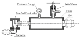
In recent years, due to the uneven water abundance of the aquifer and the complexity of the underground seepage field, the grouting reconstruction project of coal mining enterprises is more difficult. The previous method is to install a high-pressure ball valve before the grouting pipe connected to the grouting pump is connected to the mixing device, which can be manually adjusted when the number of grouting pumps needs to be changed. However, under certain pressure, the ordinary high-pressure ball valve often fails due to the influence of high-pressure mixed slurry, cement solidification and wear, and the number of grouting pumps cannot be increased or decreased in real time. In order to solve the problem that the mixing device of traditional grouting system is easy to fail by using ordinary high-pressure ball valve, the mixing device of free ball check valve was developed and applied in the process of treating the Ordovician limestone aquifer area on the floor of No.9 coal seam in Xipang Well. The practical results show that the pipeline can be automatically closed when a single grouting pump stops grouting, and there is no need to flush the grouting pipeline with a large amount of water, which can improve the grouting efficiency and quality, and the influence time of single hole section is reduced from 8.25h to 0.34h. The process performance can meet the requirements of efficient grouting.
| Published in | Applied Engineering (Volume 8, Issue 1) |
| DOI | 10.11648/j.ae.20240801.14 |
| Page(s) | 41-46 |
| Creative Commons |
This is an Open Access article, distributed under the terms of the Creative Commons Attribution 4.0 International License (http://creativecommons.org/licenses/by/4.0/), which permits unrestricted use, distribution and reproduction in any medium or format, provided the original work is properly cited. |
| Copyright |
Copyright © The Author(s), 2024. Published by Science Publishing Group |
Directional Drilling Rig, Regional Governance, Grouting Transformation, Free Ball Check Valve, Mixing Plant
2.1. Grouting Mixing Device Definition
2.2. Analysis of Problems in Traditional Schemes
2.3. Design of Free Ball Check Valve
2.4. Design and Installation of Free Ball Check Valve Mixing Device
3.1. Project Profile
3.2. Grouting Technique
Transmission Gear | 1 | 2 | 3 | 4 | 5 |
|---|---|---|---|---|---|
Rated Flow (m³/h) | 3 | 5.5 | 10.2 | 15 | 23.3 |
Rated Discharge Pressure (MPa) | 11 | 11 | 11 | 11 | 8 |
Transmission Gear | 1 | 2 | 3 | 4 | 5 |
|---|---|---|---|---|---|
Rated Flow (m³/h) | 1.7 | 2.7 | 4.6 | 7.5 | 11.2 |
Rated Discharge Pressure (MPa) | 10 | 10 | 10 | 10 | 7 |
3.3. Comparative Analysis of Application Effect
Hole Number | Length of hole section (m) | Number of grouting sections | Pump withdrawal (change) times | Frequency of maintenance |
|---|---|---|---|---|
Ground 2-1 | 687 | 5 | 10 | 11 |
Ground 2-2 | 414.06 | 3 | 6 | 7 |
Ground 2-3 | 684.87 | 5 | 10 | 10 |
Ground 2-4 | 767.87 | 6 | 12 | 11 |
Ground 1-1 | 1062.17 | 8 | 16 | 18 |
Ground 1-2 | 966.21 | 7 | 14 | 15 |
Ground 1-3 | 851.83 | 6 | 12 | 13 |
Total | 5434.01 | 40 | 80 | 85 |
Hole Number | Length of hole section (m) | Number of grouting sections | Pump withdrawal (change) times | Frequency of maintenance |
|---|---|---|---|---|
Ground 2-5 | 1331.02 | 9 | 18 | 16 |
Ground 2-6 | 598.67 | 4 | 8 | 10 |
Ground 2-7 | 682.68 | 5 | 10 | 12 |
Total | 2612.37 | 18 | 36 | 38 |
3.4. Benefit Analysis
| [1] | Dong Shuning, Guo Xiaoming, Liu Qisheng, etc. Advanced regional control mode and selection criteria of limestone aquifer in the floor of North China type coalfield [J]. Coalfield geology and exploration, 2020, 48(04): 1-10. |
| [2] | Jin Mingfang, Shen Qingchun, Xie Wei. Study on the combination of drilling and geophysical exploration to determine the attributes of large and medium-sized faults [J]. Coal Engineering, 2013, 45(10): 100-101 + 105. |
| [3] | Guo Bing, Chen Yuhua, Zhang Hairong. Research and Application of Grouting Reinforcement and Reconstruction Technology for Limestone Confined Aquifer in Coal Floor [J]. Coal and Chemical Industry, 2019, 42(10): 48-51 + 55. |
| [4] | Yao Yu. Application of ground directional bedding drilling in grouting transformation of aquifer in floor of mining face [J]. Modernization of coal mine, 2020, No. 157(04): 185-187 + 190. |
| [5] | Dou Wenjiao, Sun Fengwei, Jiang Xianxian, etc. Analysis and Improvement of Flange Leakage in High Pressure Ball Valves [J]. Valves, 2020, No. 232(06): 47-49. |
| [6] | Shi Yuheng, Li Chun, Wang Chunsheng, etc. Research on erosion wear failure of ball valves considering gas-solid two-phase flow [J]. Thermal Power Engineering, 2022, 37(07): 116-124. |
| [7] | Luo Zhijun. Analysis and Selection of High Pressure Ball Valves for Ebullated Bed Residue Hydrogenation Unit [J]. Valves, 2020 (03). |
| [8] | Zhang Yanchao, li Dongfeng, li Guocai. Cause analysis and maintenance of hydraulic control check valve failure [J]. Equipment management and maintenance, 2020 (23). |
| [9] | Wang Xuesong, Cheng Hua, Yao Zhishu, etc. Theoretical Research on Grouting in Deep Loose Layers Based on the Cylindrical Diffusion Model of Radial Tube Flow [J]. Geofluids, 2022. |
| [10] | Wang Xuesong, Cheng Hua, Yao Zhishu, etc. Theoretical Research on Sand Penetration Grouting Based on Cylindrical Diffusion Model of Tortuous Tubes [J]. Water, 2022. |
| [11] | Guo Tingting, Zhang Zhiwei, Yang Zhiquan, etc. Penetration Grouting Mechanism of Time-Dependent Power-Law Fluid for Reinforcing Loose Gravel Soil [J]. Minerals, 2021. |
| [12] | Fatiha Bouchelaghem. Multi-scale modelling of the permeability evolution of fine sands during cement suspension grouting with filtration [J]. Computers and Geotechnics, 2009. |
| [13] | Cheng Hua, cao Rukang, liu Xiangyang. Experimental study on mechanical properties and microscopic characteristics of new grouting materials [J]. Journal of Anhui University of Science and Technology (Natural Science Edition), 2022 (02). |
| [14] | Xing Wenping, li Wenjun, zhang He. Application of underground mobile grouting pressure technology [J]. Zhongzhou Coal, 2013 (12). |
| [15] | Nie Xinming, wang Mengguo, dai Xiaoguang, etc. Development and application of high pressure grouting pipeline mixing device for free ball check valve [J]. Chemical Mineral Geology. 2021, 43(02). |
APA Style
Liu, Y. (2024). Application of Free Ball Check Valve Mixed Grouting Device. Applied Engineering, 8(1), 41-46. https://doi.org/10.11648/j.ae.20240801.14
ACS Style
Liu, Y. Application of Free Ball Check Valve Mixed Grouting Device. Appl. Eng. 2024, 8(1), 41-46. doi: 10.11648/j.ae.20240801.14
AMA Style
Liu Y. Application of Free Ball Check Valve Mixed Grouting Device. Appl Eng. 2024;8(1):41-46. doi: 10.11648/j.ae.20240801.14
@article{10.11648/j.ae.20240801.14,
  author = {Yifang Liu},
  title = {Application of Free Ball Check Valve Mixed Grouting Device
},
  journal = {Applied Engineering},
  volume = {8},
  number = {1},
  pages = {41-46},
  doi = {10.11648/j.ae.20240801.14},
  url = {https://doi.org/10.11648/j.ae.20240801.14},
  eprint = {https://article.sciencepublishinggroup.com/pdf/10.11648.j.ae.20240801.14},
  abstract = {In recent years, due to the uneven water abundance of the aquifer and the complexity of the underground seepage field, the grouting reconstruction project of coal mining enterprises is more difficult. The previous method is to install a high-pressure ball valve before the grouting pipe connected to the grouting pump is connected to the mixing device, which can be manually adjusted when the number of grouting pumps needs to be changed. However, under certain pressure, the ordinary high-pressure ball valve often fails due to the influence of high-pressure mixed slurry, cement solidification and wear, and the number of grouting pumps cannot be increased or decreased in real time. In order to solve the problem that the mixing device of traditional grouting system is easy to fail by using ordinary high-pressure ball valve, the mixing device of free ball check valve was developed and applied in the process of treating the Ordovician limestone aquifer area on the floor of No.9 coal seam in Xipang Well. The practical results show that the pipeline can be automatically closed when a single grouting pump stops grouting, and there is no need to flush the grouting pipeline with a large amount of water, which can improve the grouting efficiency and quality, and the influence time of single hole section is reduced from 8.25h to 0.34h. The process performance can meet the requirements of efficient grouting.
},
 year = {2024}
}
TY  - JOUR
T1  - Application of Free Ball Check Valve Mixed Grouting Device

AU  - Yifang Liu
Y1  - 2024/04/17
PY  - 2024
N1  - https://doi.org/10.11648/j.ae.20240801.14
DO  - 10.11648/j.ae.20240801.14
T2  - Applied Engineering
JF  - Applied Engineering
JO  - Applied Engineering
SP  - 41
EP  - 46
PB  - Science Publishing Group
SN  - 2994-7456
UR  - https://doi.org/10.11648/j.ae.20240801.14
AB  - In recent years, due to the uneven water abundance of the aquifer and the complexity of the underground seepage field, the grouting reconstruction project of coal mining enterprises is more difficult. The previous method is to install a high-pressure ball valve before the grouting pipe connected to the grouting pump is connected to the mixing device, which can be manually adjusted when the number of grouting pumps needs to be changed. However, under certain pressure, the ordinary high-pressure ball valve often fails due to the influence of high-pressure mixed slurry, cement solidification and wear, and the number of grouting pumps cannot be increased or decreased in real time. In order to solve the problem that the mixing device of traditional grouting system is easy to fail by using ordinary high-pressure ball valve, the mixing device of free ball check valve was developed and applied in the process of treating the Ordovician limestone aquifer area on the floor of No.9 coal seam in Xipang Well. The practical results show that the pipeline can be automatically closed when a single grouting pump stops grouting, and there is no need to flush the grouting pipeline with a large amount of water, which can improve the grouting efficiency and quality, and the influence time of single hole section is reduced from 8.25h to 0.34h. The process performance can meet the requirements of efficient grouting.

VL  - 8
IS  - 1
ER  -
Coal Science (Beijing) New Materials Technology Co. Ltd, Beijing, China
Information