Research Article | | Peer-Reviewed

Thermal Analysis and Simulation of an Uncovered Flat-plate Solar Collector with Parallel Tubes

Received: 27 April 2025     Accepted: 8 June 2025     Published: 23 June 2025
Views:       Downloads:
Abstract

The use of low-temperature solar thermal energy is of vital importance to households both in temperate zones for heating and in Sahelian zones for domestic hot water. This study focuses on the thermal analysis and simulation of an uncovered flat plate collector with parallel tubes using water as the heat transfer fluid. It is based on the analysis of the thermal performance and the careful selection of each component of the system, namely the coating, the absorber, and the insulator, to obtain optimal operation of the solar collector. The equations are presented in such a way that they can be easily solved by programming in the structured language MATLAB. The Newton-Raphson method was used to determine the temperature of the absorber wall after obtaining a nonlinear equation. Unlike stainless steel and Aluminum, the copper absorber does not store enough energy in itself, but transmits most of the energy flow to the heat transfer fluid, resulting in outlet temperatures of 82.62°C from a 2m tube, making copper the most suitable material for an absorber. TINOX and black chrome are better quality coatings, with a tube outlet temperature of 82.9°C, while that of the selective black plate is 80.12°C. The study also involved a comparative analysis of the thermal system with four types of insulation at the tube outlet. The water temperature ranged from 81.56°C to 82.32°C with insulation, meanwhile it was 73.37°C without insulation. As the fluid inlet temperature approaches ambient temperature, collector efficiency increases until it attains a maximum value of 62%.

Published in International Journal of Sustainable and Green Energy (Volume 14, Issue 2)
DOI 10.11648/j.ijsge.20251402.14
Page(s) 99-112
Creative Commons

This is an Open Access article, distributed under the terms of the Creative Commons Attribution 4.0 International License (http://creativecommons.org/licenses/by/4.0/), which permits unrestricted use, distribution and reproduction in any medium or format, provided the original work is properly cited.

Copyright

Copyright © The Author(s), 2025. Published by Science Publishing Group

Keywords

Flat-plate Collector, Useful Energy Gain, Surface Coating, Insulation, Absorber, Heat Transfer Fluid, Temperature

1. Introduction
One of the most pressing global challenges today is to promote sustainable environmental policies and low-carbon economies in emerging and developed countries. This involves improving the performance of previously energy-intensive systems while proposing new technological approaches based on scientific research . In a context of fossil fuel depletion and renewable energy growth , households and energy-consuming industries are turning to modular solar technologies for decentralized energy production . Energy plays an essential role in the functioning of our modern societies, supporting all human activities . The thermal use of solar energy to produce heat from sunlight is one of the oldest energy conversion methods. This technology has been known and sometimes even used unknowingly since time immemorial. It has been rediscovered and reused in the last 45 years. Today, it is ready for application, but after this short period of growth, there is great potential for development in this field, especially in solar collectors . The solar thermal collector is the main component in any solar thermal application. It absorbs incoming solar radiation, converts it into heat, and transfers the heat to a working fluid (usually air, water, or oil) flowing through it . A solar collector is a special type of heat exchanger that converts solar radiation into heat. Without optical concentration, the flux of incident radiation is at best around 1100 W/m2 and is variable. Different types of solar collectors are available, such as evacuated tube solar collectors, flat plate solar collectors, and parabolic trough solar collectors . Flat-plate solar collectors can be designed for applications where energy is required at moderate temperatures, up to 100°C above ambient. They both use direct and diffuse solar radiation, do not require tracking of the sun, and require little maintenance. The main applications of these devices are solar water heating, space heating, air conditioning, and industrial process heating . Several researchers have worked on the design and development of flat plate collectors . Matrawy and Farkas studied the important role of the collector configuration and its thermal performance . The parallel tube collector design is one of the most commonly used configurations, in which tubes (risers) are integrated with the absorber plate and form an integral part of the plate structure . Hashim describes the performance of solar water heating for flat plate collectors . Azimy et al. increase the heat transfer surface of the collector pipe in contact with the absorber plate at the flat-plate solar collector by designing the pipe in a zigzag shape instead of conventional straight pipe Another study has been carried out to analyze the collector efficiency of the solar water heater with a rectangular tube configuration and recycle operation. Amar et al. investigate the effects of novel green covalently functionalized gallic acid-treated multiwall carbon nanotube water nanofluid on the performance of flat plate solar collectors .
This study focuses on the flat-plate solar water collector with parallel tubes and no cover. The working principle is as follows: sunlight passes through the air to the absorber, which converts the solar energy into heat and transfers the heat to the heat transfer fluid, completing the solar thermal conversion process. During the heat transfer process, the collector will lose some of its heat through conduction, convection, and radiation. So, how can these losses be minimized to optimize collector operation? This study analyses the thermal performance of an uncovered solar water collector with parallel tubes in the center of the plate and shows the role of parameters such as coating, collector material, and insulation in achieving optimal operation of the solar collector.
2. Materials and Methods
As illustrated in Figure 1, the schematization of convective flows in an uncovered solar collector is presented.
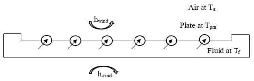
Figure 1. Schematization of convective flows in an uncovered solar collector.
Heat losses on the top and bottom of the absorber plate are defined by:
Heat losses on the top: φ
φ= hwind+hr,a-pTp-TaS (W)(1)
Heat losses on the bottom: φ
φ= Tp-Taeiλi +1hwind  S (W) (2)
Total heat losses φt are obtained (1) and (2), according to the equations.
φt=φ+φ= hP Tp-TaS(W)(3)
hP=hwind+hr,a-p+ 1eiλi +1hwind  (W.m2.°C-1)(4)
hP represents the total heat loss coefficient.
Where
(1) hwind: Represents the convection heat-transfer coefficient between the absorbing plate and the air;
(2) hr,a-p: Represents the radiative heat transfer coefficient between the plate and the air.
The calculation of hwind and hr,a-p is performed using the correlations (5) and (6):
Convection on the flat face: air
hwind=1.32T-TaL0.25 if 104<Gra.Pra and  Gra.Pra <109  1.52T-TaL13 else (5)
where,
(1) Gra and Pra: Successively represent the number of Grashof and the Prandtl number of air;
(2) T and Ta: Successively represent the plate temperature and the air temperature;
(3) L: represents the length of the plate.
hr,p-a= σεT2+Ta2(T+Ta)(6)
The exchange between the tube and the heat transfer fluid is defined by the exchange coefficient hi whose calculation is done by the following correlation, knowing that in the case of tubes, the heat transfer fluid used is generally water .
hi=λ.NuDi(7)
With
Nu=0.023Ree0.8.Pre0.3 if Ree>5000 and  0.6<Pre<100  1.86.Ree.Pre13.DiL13. μμP0.14 else (8)
φu:Useful energy gain
2.1. Useful Energy Transferred to the Fluid
Initially, the temperature profile of the absorber plate in the Oy direction, perpendicular to the Ox direction of the fluid flow (as illustrated in Figure 2), will be determined.
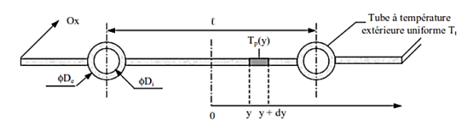
Figure 2. Equivalent electrical diagram of heat transfers in a flat-plate solar collector with parallel tubes in terms of radiation, convection and conduction resistances .
The general temperature distribution on an absorber plate (fin) in the (0y) direction is illustrated in Figure 3.
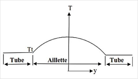
Figure 3. Temperature distribution on an absorber plate.
The heat balance of the piece of plate of unit length between y and y + dy (Figure 3) is written (Eq. 9):
hPλpepTP-Ta-ϕsahP=d2Tdy2(9)
where ′ep′ 𝑟𝑒𝑝𝑟𝑒𝑠𝑒𝑛𝑡s the thickness of the plate.
The boundary conditions for the absorbing plate are presented in the following form
y=0, d(TP-Ta-ϕsahP) dy=0 andy=l-De2, Tp=Tt where Tt is the heat transfer temperature.
The general solutions of Eq.9 is the distribution function of fluid temperature across the tube can be given by the equation (10):
Tpy-Ta-ϕsahPTt-Ta-ϕsahP= coshωycoshωl-De2(10)
The fin efficiency is defined by (Eq. 11):
F=tanhωl-De2ωl-De2(11)
The tube region also gains a heat flux directly absorbed on its apparent width De assumed at a uniform temperature of Tt. The energy gain for this region is (Eq. 12):
t= De.ϕsa-hpTt-Ta(12)
The total useful energy gained by a tube per unit length in the direction (Ox) of fluid flow is written by (Eq 13):
u =lF'ϕsa-hpTf-Ta W.m-1 (13)
where the collector efficiency factor F’ is given as (Eq. 14)
F'=1hpl1De+Fl-De+1hiπDi+etλiπDi(14)
2.2. Temperature Distribution in Flow Direction (Ox)
Consider a tube of length L among the n tubes of the collector, the fluid enters the tube at temperature Tfe and increases in temperature until at the exit it is Tfs. According to the above, each tube gains a useful flux of  u per unit length in the Ox direction of fluid flow. The expression of the energy balance for a fluid flowing through a single tube of length dy is given by equation (Eq. 15):
ṁfnCfdTdx=udx = lF'ϕsa-hpTf-Tadx(15)
Where,
ṁf kg.s-1 is the total collector flow rate and n is the number of parallel tubes; Cf is the Fluid specific heat (J. kg-1.k-1).
Assuming F' and hp are position independent, the solution for the fluid temperature at any position x is (eq. 16):
Tfx-Ta-ϕsahPTfe-Ta-ϕsahP=exp-nlF'hpṁfCfx(16)
If the collector has a length L in the flow direction, then the fluid outlet temperature Tfs is found by substituting L for x in Eq. 16. The quantity nlL=S is the collector area:
Tfs-Ta-ϕsahPTfe-Ta-ϕsahP=exp-SF'hpṁfCf(17)
The average fluid temperature in the absorber can also be obtained from Eq. 18:
Tfmoy=1L0tTfxdx =Ta+ϕsahP+ṁfCfnSF'hpTfe-Ta-ϕsahP1-exp-SF'hpṁfCf(18)
2.3. Useful Energy Gain
The useful energy gained by the collector area (S) can be calculated by Eq. 19:
φu=n0Ludx=SFRϕsa-hpTfe-Ta(19)
Where FR, the collector heat removal factor can be expressed as (Eq. 20)
FR=ṁfCfS hp1-exp-SF'hpṁfCf(20)
The overall efficiency of the sensor is finally written as:
The overall collector efficiency is finally written as (Eq. 21):
η=FRη0-hpTfe-TaGi,γ*(21)
η0 is the optical efficiency.
The equivalent electrical diagram of the different heat transfers is shown in Figure 4.
The heat balance at the node level is written
φsp=Tp-TaR6+Tp-TaR5+φuS(22)
With, R1=R4=1hwind, R2=eiλi, R3=1hr,c-a
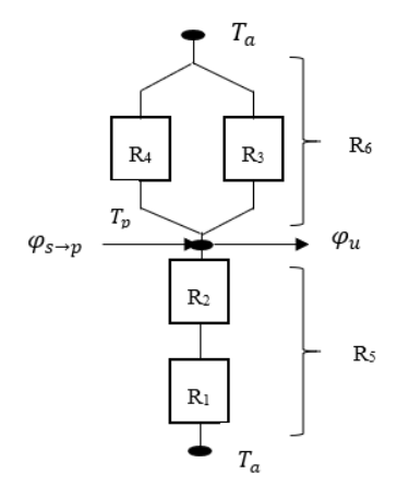
Figure 4. Equivalent electrical diagram of heat transfers in a flat-plate solar collector with parallel tubes and no cover in terms of conduction, convection, and radiation resistances.
This leads to a nonlinear equation (Eq. 23) whose unknown is Tp
f(Tp)=φsps+Tp-Tahwind+σαpTp4-εaTa4Tp-Ta+Tp-Ta1hwind+eλ+FRΦsa-1eλ+1hwind+hwind+σαpTp4-εaTa4Tp-Ta(Tfe-Ta)=0(23)
To determine this temperature, Newton-Raphson's method of solving will be used.
The algorithm of this method is defined by (Eq. 24):
Tp(k)=Tp(k-1)-fTp(k-1)/fTp(k-1)/Tp(24)
where k is the number of iterations. This iteration is performed once an initial value is given to Tp (1). The iteration will stop when two consecutive values of temperature satisfy the following condition: Tp(k)-Tp(k-1)ε
where is the tolerance. The derivative of the characteristic function f (Tp) with respect to the temperature Tp is given by relation (25):
fTpk-1Tp=hwind+4σ.αpTp3k-1+11hwind+eλ-FRσαp3Tp4k-1+εaTa4-4TaTp4k-1Tpk-1-Ta2Tfe-Ta (25)
MATLAB software is used to implement this resolution.
Determining the collector parameters (fin temperature, heat transfer fluid temperature, useful energy gain, etc.) requires first determining the collector overall loss coefficient (hp). This value depends on the average absorber temperature (Tm) because the temperature on the collector surface is not uniform (Figure 3). It is necessary to arbitrarily set the values of Tpo (collector plate temperature at the initial point) and Tt (fin temperature at the point of transfer with the tubes) such that Tp is only a few degrees higher than Tt because the fins are small. The average collector plate temperature is determined by the following equation 26:
Tm=TPo+Tt2(26)
Similarly, the convection coefficient in the tubes also varies with the water temperature (Te). Therefore, it is necessary to arbitrarily determine the average water temperature in the tubes based on the inlet temperature Te and the outlet temperature Te(Eq. 27).
Te=Tfe+Tfs2(27)
ThefluidoutlettemperaturewillbeatTfs=80 ℃.Hence,Te=Tfe+802
2.4. Absorber
The main role of an absorber is to capture solar radiation and convert it into heat energy. It is generally painted black to absorb all radiation in the visible and ultraviolet spectrum, and a small proportion in the infrared. The absorber is chosen for its good absorption coefficient, thermal conductivity, and corrosion resistance.
The absorbers in Table 1 were selected for this study:
Table 1. Properties of the absorbers used .

Matérial

ρ (Kg.m-3)

λ (w.m-1.-1)

Cp (J.kg-1.-1)

Copper

8954

386

383

Aluminium

2707

204

896

Stainless steel

7833

14

465

2.5. Heat Transfer Fluids
To evacuate the heat stored by the absorbent sheet, either water or air is generally used as a heat transfer fluid.
In this study, water will be used as a heat transfer fluid.
2.6. Insulation
A collector must be well thermally insulated, and this with an appropriate material. These must have a very low thermal conductivity to minimize thermal losses by conduction through the faces of the collector. Mineral wools, synthetic materials (glass wool, expanded foams, polyurethane, or polystyrene) are generally the insulating materials used.
Table 2 summarizes the properties of the most commonly used insulators.
Table 2. Matériaux isolants et leurs propriétés .

Isulator

Thermal Conductivity

Maximum Temperature

Glass wool

0.041

150

Rockwool

0.05

150

Polyurethane

0.027

110

Polystyrene

0.039

85

Expanded cork

0.042

110

2.7. Surface Coating
Since absorbers are made of metal: copper, aluminum, or stainless steel, and since metal surfaces tend to reflect light, absorbers must be coated with a coating also called anti-reflection coating that strongly absorbs the wavelengths of solar radiation to produce maximum heat for heating. The major characteristics of coating are absorber plate α and absorber plate emissivity ε.
At the beginning of the technology, especially developed black solar paints were used, then selective coatings that reduced thermal losses.
Modern coatings used are: Nickel/Black Chrome, black crystal, PVD (Physical Vapor Deposition), PECVD (Plasma Enhanced Chemical Vapor Deposit).
The objective is to determine the coating that offers the best optical efficiency and the best heat transfer fluid temperature.
The Optical efficiency is given by:
ηo= τv*αre*G*G*=τv*αre(28)
Where, τv Glass transmission coefficient.
αre The absorber plate absorptivity.
The system does not possess a glass cover (τv=1), and thus the following equation is applicable:
ηo=αre(29)
3. Results
Simulation parameters are summarized in Table 3.
Table 3. Simulation parameters.

Parameters

Value/unit

Irradiance

1000 W.m2

Plate temperature Tt0

100 ℃

Length of a segment L

2m

Distance between the tube l

15 cm

Number of tubes n

14

Absorber plate thickness ep

1 mm

Tube outside diameter De

11 mm

Tube inside diameter Di

10 mm

Fluid mass flow rate ṁ

0.014 kg/s

Fluid specific heat Cp

4180 W/m2

Insulation thickness

4 cm

3.1. Influence of the Coating
The anti-reflective coating is a significant component of the collector. In essence, it quantifies the extent of solar energy absorbed by the system. The selection was made for three commonly used coatings: selective black plate, black chrome, and TINOX. The central question guiding this study is to ascertain which of these coatings offers the optimal optical performance and the highest heat transfer fluid temperature.
Figure 5 shows the impact of the nature of the coating on the temperature of the heat transfer fluid in its flow direction through a tube. It is evident that the heat transfer fluid exhibits varying temperatures, contingent upon the nature of the coating in question. At the outlet of the tube and with a TINOX or black chrome coating, the heat transfer fluid temperature is 82.9°C; when using a selective black plate, the temperature is 80.12°C; finally, when there is no selective coating (bare copper), the temperature is 43.93°C. This result is justified when calculating the optical efficiency of these different coatings (Table 4): the coating with the highest optical efficiency is the one that increases the fraction of solar energy absorbed the most.
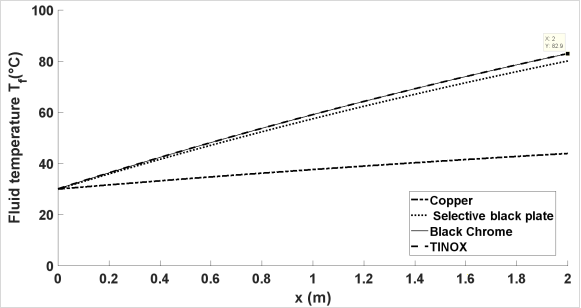
Figure 5. Influence of the coating on the temperature profile of the fluid in the flow direction (0x).
Choosing a coating with high selectivity is also important, meaning the fraction of absorbed radiation should be significantly higher than the fraction emitted by infrared radiation. This would ensure a maximum temperature at the fins.
Table 4. Optical efficiency.

Coating

Optical efficiency (%) (Eq. 35)

Copper without coating)

5

Selective black plate

90

Black Chrome

95

TINOX

95

It has been established that, contingent upon the nature of the coating (Figure 6), black chrome and TINOX facilitate a greater transmission of energy to the heat transfer fluid compared to a selective black plate.
The best coatings are therefore TINOX and black chrome. The choice of one or the other depends on the manufacturing process and economic constraints.
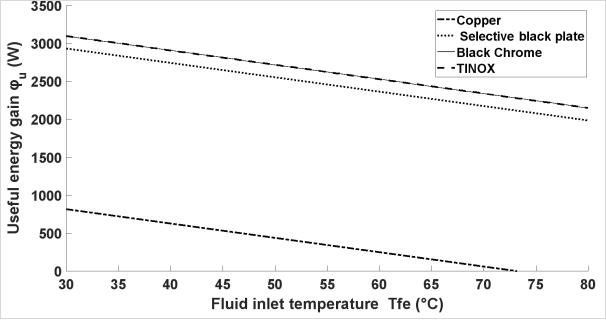
Figure 6. Influence of the coating on the useful energy gain as a function of the heat transfer fluid inlet temperature.
3.2. Influence of the Nature of the Absorber Plate
The selection of the absorber constitutes a pivotal phase in the sizing of a collector. The absence of glass necessitates the selection of a material with both good thermal conductivity and diffusivity. Indeed, the absorber must be capable of swiftly transferring the energy received to the tubes. The most commonly used materials are copper, stainless steel and aluminum. Iron is not utilized due to its propensity for oxidation.
Figure 7 describes the temperature distribution of the absorber plate between two consecutive tubes. The temperature contribution of the fins decreases from the middle of the space separating the two tubes. We observe that stainless steel has a much better temperature at its fins than aluminum; Copper is the material with the lowest temperature. These observations reflect their heat accumulation capacity in the material.
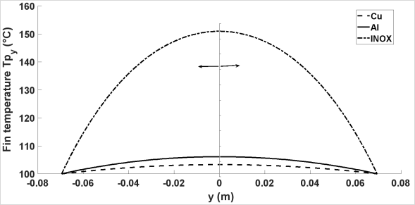
Figure 7. Influence of the nature of the absorber plate on the fin temperature profile.
The temperature of stainless steel (INOX) is higher, but it has lower diffusivity (Table 5). Therefore, it poorly transmits the received energy, which creates heat accumulation within it, hence its high temperature compared to aluminum and copper.
Table 5. The thermal diffusivity of the absorber plate used.

Absorber plate

Diffusivity (a=λρcp ×10-6m2.s)

Copper

108

Aluminium

86

Stainless steel

4

Figure 8 shows the fluid temperature profile in its flow direction. When copper is used, the outlet fluid temperature is better throughout the tube, reaching a value of 82.62°C at its outlet; aluminum comes next with 81.85°C, and finally INOX with 67.99°C.
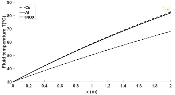
Figure 8. Influence of the nature of the absorber plate on the heat transfer fluid temperature profile in the direction of fluid flow.
It follows that, depending on the nature of the collector material used, the heat transfer capacity to the fluid is better when copper is used.
Aluminum comes next; finally, INOX.
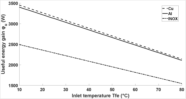
Figure 9. Influence of the nature of the absorber plate on the useful energy gain as a function of the heat transfer fluid inlet temperature.
Figure 9 describes the useful energy transferred by the collector to the fluid depending on the latter's inlet temperature. Taking into account the heat transfer capacity, copper, aluminum, and stainless steel are, in descending order, the materials that diffuse the most useful energy to the heat transfer fluid.
3.3. Influence of Collector Plate Thickness and Tube Spacing
It is a matter of evaluating the impact of collector plate thickness and tube spacing on the efficiency of the fins.
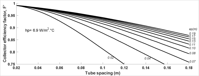
Figure 10. Fin efficiency as a function of tube spacing and absorber thickness.
It can be seen from Figure 10 that the larger the thickness (ep) and the smaller the space between the tubes (l), the better the collector efficiency, F'.
These two parameters act, therefore, simultaneously on the fin efficiency and its temperature. Indeed, the fin temperature is a function of the spacing between the tubes and the absorber thickness.
3.4. Insulation
The purpose is to study the influence of the nature of the insulation on the behavior of the system. In this section, copper is used as the absorber.
Figure 11 illustrates the temperature profile of a fin when different types of insulation are used. In the middle of the space separating the two tubes, the absorber temperature varies very slightly from 104.7 to 105.0°C with an insulation system. The fin then gains 4.2 to 4.5°C in temperature compared to an insulation system.
It appears that polyurethane is the best insulator, which allows for storing heat in the collector plate; polystyrene, glass wool, expanded cork, and rock wool come next, respectively. Thus, the choice of insulation also depends on its maximum operating temperature, as shown in Table 2.
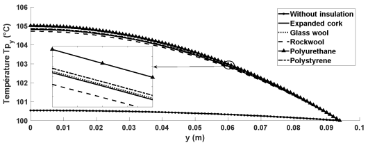
Figure 11. Fin temperature profile.
Figure 12 shows the fluid temperature profile in the direction of flow when using different types of insulation. The tube outlet temperature varies from 81.56°C to 82.32°C with insulation. Without insulation, this temperature is 73.37°C. It is therefore imperative to use insulation that will prevent heat loss.
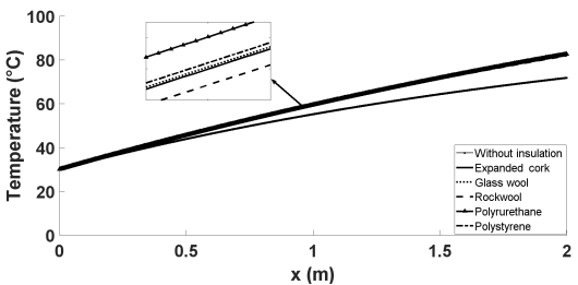
Figure 12. Temperature profile along the flow.
The heat transfer fluid exits the system with a temperature close to 82°C (Figure 12): the system effectively functions as a low-temperature thermal collector.
As illustrated in Figure 13, the useful energy transferred by the collector to the fluid is contingent on the inlet temperature of the latter, and this is the case for different types of insulation. It has been demonstrated that the useful energy is higher when using polyurethane, followed by polystyrene, glass wool, expanded cork, and rock wool in decreasing order.
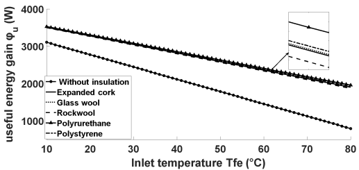
Figure 13. Influence of the nature of the insulation on the useful energy gain as a function of the inlet temperature of the heat transfer fluid.
Polyurethane is the best insulator, but it can only be used at relatively low temperatures (see Table 2). With a view to the results obtained, the type of insulation used has a small influence on the output characteristics of the insulated system. Consequently, the most appropriate insulation is that which can withstand a maximum operating temperature that exceeds the system's internal temperature (plate temperature). The dimensional parameters of the collector are the determining factor in this regard.
3.5. Variation of the Collector Efficiency as a Function of the Inlet Temperature
The curve below shows the variation in collector efficiency as a function of the inlet temperature of the heat transfer fluid.
As demonstrated in Figure 14, for a constant ambient temperature and irradiance, the collector efficiency is optimized when the heat transfer fluid temperature is in closer proximity to the ambient air temperature.
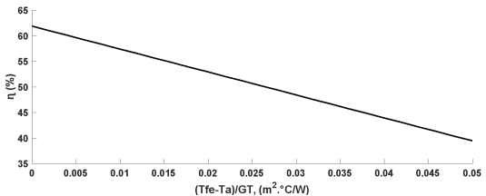
Figure 14. Variation of the collector efficiency as a function of inlet temperature.
However, this efficiency decreases as the fluid inlet temperature is higher than the ambient temperature. This is why one should not seek high heat transfer fluid temperatures with a flat plate.
As demonstrated in Figure 15, deviation of the efficiency curve is observed compared to Figure 14: the heat transfer coefficient, hp, and the collector heat removal factor, FR, are no longer considered constants. In reality, these parameters (hp and FR) vary with the operating temperature and solar radiation.
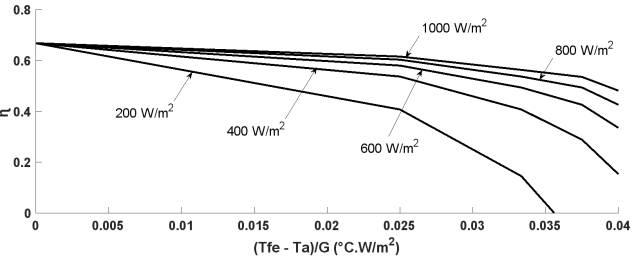
Figure 15. Real curve of the flat plate collector.
This result is usually obtained under experimental conditions that reflect the real operating state of a flat plate collector.
4. Conclusions
The present study is predicated on the analysis of the thermal performance of an uncovered flat plate solar collector with parallel tubes. The effectiveness of the collector is contingent upon optimization of its constituent subsystems. The following conclusions are drawn from the analysis:
(1) The most efficacious coatings are TINOX and black chrome.
(2) Given the elevated diffusivity and selectivity exhibited by copper, it is considered optimal for use as an absorber plate.
(3) Any thermal system must be insulated, irrespective of the nature of the insulation provided, on the condition that its operating temperature range coincides with the temperature range of the collector.
(4) The collector efficiency, F', is optimized when the thickness of the absorber (ep) is substantial and the spacing between the tubes (l) is diminished.
(5) The collector efficiency is optimized when the heat transfer fluid temperature is closer to the ambient air temperature.
When the heat transfer coefficient hp and the heat removal factor FR are no longer considered constant and vary with operating temperature and solar radiation, the efficiency curve deviates and behaves as it does in real operation.
The optimal functioning of an uncovered flat-plate solar collector with parallel tubes is contingent on the judicious selection of a suitable coating. TINOX or black chrome has been identified as the most appropriate option in this specific instance. These coatings are to be applied to a copper absorber plate that is to be protected by an insulator. However, to enhance the heat flux transmitted to the heat transfer fluid, optimizing the heat transfer coefficient to the fluid would be judicious. One potential solution to this issue would be to modify the geometric configuration of the tubes.
Abbreviations

Cf

Fluid Specific Heat

Cp

Specific Heat Capacity, J/kg°C

De, Di

External Diameter, Internal Diameter of a Parallel Tube, Hydraulic, m

F

Fin Efficiency Factor

F’

Collector Efficiency Factor

FR

Heat Removal Factor

G

soLar Radiation Incident on Absorber, Maximum Solar Radiation, W/m2

g

Gravitational Constant, m/s2

hc, hr, hwind

Heat Transfer Coefficient: Convection, Radiation, from Wind, W/m2°C-1

hi

Heat Transfer Coefficient Inside Tube, W/m2°C-1

L

Length of Collector, m

n

Number of Glass Covers

Pr

Prandtl Number

Nu

Nusselt Number

Gr

Grashof Number

Re

Reynolds Number

Tp

Cover Temperature, Mean Plate Temperature, _C

Tfe,

Tfs Fluid Input Temperature, Fluid Output Temperature, C

hp

Coefficients: Heat Loss, Collector Overall Heat Loss, Top Loss, W/m2°C-1

l

Tube Spacing, Width of Collector, m

ep

Absorber Plate Thickness, m

G*

Irradiance W/m2 Greek Letters

λ

Thermal Conductivity, W/m°C

ρu

Heat Useful Gain, W/m2

ε

Absorber Plate Emissivity

σ

Absorber Plate Absorptivity

φu

Useful Energy Gain (W)

τ

Glass Transmission Coefficient

ɳ0

Optical Efficiency

ṁ

Total Collector Flow Rate, kg.s-1

Author Contributions
Deli Goron: Conceptualization, Data curation, Formal Analysis, Investigation, Methodology, Project administration, Resources, Supervision, Writing – original draft, Writing – review & editing
Ayang Albert: Conceptualization, Data curation, Software, Validation, Writing – review & editing
Funding
This work is not supported by any external funding.
Data Availability Statement
The data is available from the corresponding author upon reasonable request.
Conflicts of Interest
The authors declare no conflicts of interest.
References
[1] Elia, A., Kamidelivand M, Rogan, F., Gallachóir, BÓ, Impacts of innovation on renewable energy technology cost reductions. Renewable and Sustainable Energy Reviews, 2021, vol. 138, p. 110488.
[2] Husin, H., Zaki, M., A critical review of the integration of renewable energy sources with various technologies, Protection and Control of Modern Power Systems 2021, 6(1), 1–18,
[3] Levenda, A. M., Behrsin, I., Disano, F., Renewable energy for whom? A global systematic review of the environmental justice implications of renewable energy technologies, Energy Res. Social Sci., 2021, 71 101837,
[4] Østergaard, P. A., Duic, N., Noorollahi, Y., Kalogirou, S., Renewable energy for sustainable development, Renew. Energy, 2022, 199, 1145–1152,
[5] Hashim W. M, Shomran, A. T, Jurmut, H. A, Gaaz T. S., Kadhum, A. A. H., Al-Amiery, A. A., Case study on solar water heating for flat plate collector. Case studies in thermal engineering, 2018, vol. 12, p. 666-671.
[6] Zima, W., Mika, Ł., & Sztekler, K., Numerical and Experimental Determination of Selected Performance Indicators of the Liquid Flat-Plate Solar Collector under Outdoor Conditions. Energies, 2024, 17(14), 3454.
[7] Kenfack, A. Z., Nematchoua, M. K., Simo, E., Konchou, F. A. T., Babikir, M. H., Pemi, B. A. P., Chara-Dackou, V. S., Techno-economic and environmental analysis of a hybrid PV/T solar system based on vegetable and synthetic oils coupled with TiO2 in Cameroon, Heliyon, 2024, 10, 24000,
[8] Le, T. T., Paramasivam, P., Adril, E., Le, M. X., Duong, M. T., Le, H. C., Nguyen, A. Q., Unlocking renewable energy potential: Harnessing machine learning and intelligent algorithms. International Journal of Renewable Energy Development, 2024, 13(4), 783-813.
[9] Babikir, M. H., Chara-Dackou, V. S., Njomo, D., Barka, M., Khayal, M. Y., Legue, D. R. K., Gram-Shou, J. P., Simplified modeling and simulation of electricity production from a dish/Stirling system, International journal of photoenergy, 2020, 1–14,
[10] Benchamma, S., Missoum, M., Belkacem, N. Performance of a direct-expansion solar-assisted heat pump for domestic hot water production in Algeria. International Journal of Renewable Energy Development, 2024, 13(4), 572-580.
[11] Shemelin, V., Matuska, T., Detailed Modeling of Flat Plate Solar Collector with Vacuum Glazing, International Journal of Photoenergy, Hindawi, 2017, Volume 2017, Article ID 1587592, 9 pages,
[12] Kalogirou, S., Solar thermal collectors and applications, Progress in Energy and Combustion Science, 2004, 30, 231–295.
[13] Pandey, K. M., Chaurasiya, R., A review on analysis and development of solar flat plate collector. Renewable and Sustainable Energy Reviews, 2017, 67, 641-650.
[14] Khan, M. M. A., Ibrahim, N. I., Mahbubul, I. M., Ali, H. M., Saidur, R., Al-Sulaiman, F. A., Evaluation of solar collector designs with integrated latent heat thermal energy storage: A review. Solar Energy, 2018, vol. 166, p. 334-350.
[15] Ho, C. D., Chen, T. C., Tsai, C. J., Experimental and theoretical studies of recyclic flat-plate solar water heaters equipped with rectangle conduits. Renewable Energy, 2010, vol. 35, no 10, p. 2279-2287.
[16] Natarajan, R., Gaikwad, P. R., Basil, E., & Borse, S. D., Heat enhancement in solar flat plate collectors–A review. Journal of Thermal Engineering, 2024, 10(3), 773-789.
[17] Fathabadi, H., Novel low-cost parabolic trough solar collector with TPCT heat pipe and solar tracker: Performance and comparing with commercial flat-plate and evacuated tube solar collectors. Solar Energy, 2020, vol. 195, p. 210-222.
[18] Duffie, J. A., Beckman, W. A., Solar Engineering of Thermal Processes. John Wiley & Sons, 2013.
[19] Shitzer, A., Kalmanoviz, D., Zvirin, Y., Grossman, G., Experiments with a flat plate solar water heating system in thermosyphonic flow. Solar Energy, 1979, vol. 22, no 1, p. 27-35.
[20] Gongora-Gallardo, G., Castro-Gil, M., Colmenar-Santos, A., Tawfik M, Efficiency factors of solar collectors of parallel plates for water. Solar energy, 2013, 94, 335-343.
[21] Matrawy, K. K., Farkas, I., Comparison study for three types of solar collectors for water heating. Energy conversion and management, 1997, vol. 38, no 9, p. 861-869.
[22] Shukla, R., Sumathy, K., Erickson, P., Gong, J., Recent advances in the solar water heating systems: A review. Renewable and Sustainable Energy Reviews, 2013, vol. 19, p. 173-190.
[23] Hashmi, N. I., Alam, N., Jahanger, A., Yasin, I., Murshed, M., Khudoykulov, K., Can financial globalization and good governance help turning emerging economies carbon neutral? Evidence from members of the BRICS‑T. Environ. Sci. Pollut. Res., 2023, 30, 39826–39841.
[24] Azimy, N., Saffarian, M. R., Noghrehabadi, A., Thermal performance analysis of a flat-plate solar heater with zigzag-shaped pipe using fly ash-Cu hybrid nanofluid: CFD approach. Environmental Science and Pollution Research, 2024, 31(12), 18100-18118.
[25] Amar, M., Akram, N., Chaudhary, G. Q., Kazi, S. N., Soudagar, M. E. M., Mubarak, N. M., & Kalam, M. A., Energy, exergy and economic (3E) analysis of flat-plate solar collector using novel environmental friendly nanofluid. Scientific Reports, 2023, 13(1), 411.
[26] Jannot, Y., Transferts thermiques, Ecole des Mines Nancy, 2012.
Cite This Article
  • APA Style

    Goron, D., Albert, A., Ekani, R. (2025). Thermal Analysis and Simulation of an Uncovered Flat-plate Solar Collector with Parallel Tubes. International Journal of Sustainable and Green Energy, 14(2), 99-112. https://doi.org/10.11648/j.ijsge.20251402.14

    Copy | Download

    ACS Style

    Goron, D.; Albert, A.; Ekani, R. Thermal Analysis and Simulation of an Uncovered Flat-plate Solar Collector with Parallel Tubes. Int. J. Sustain. Green Energy 2025, 14(2), 99-112. doi: 10.11648/j.ijsge.20251402.14

    Copy | Download

    AMA Style

    Goron D, Albert A, Ekani R. Thermal Analysis and Simulation of an Uncovered Flat-plate Solar Collector with Parallel Tubes. Int J Sustain Green Energy. 2025;14(2):99-112. doi: 10.11648/j.ijsge.20251402.14

    Copy | Download

  • @article{10.11648/j.ijsge.20251402.14,
      author = {Deli Goron and Ayang Albert and Roger Ekani},
      title = {Thermal Analysis and Simulation of an Uncovered Flat-plate Solar Collector with Parallel Tubes},
      journal = {International Journal of Sustainable and Green Energy},
      volume = {14},
      number = {2},
      pages = {99-112},
      doi = {10.11648/j.ijsge.20251402.14},
      url = {https://doi.org/10.11648/j.ijsge.20251402.14},
      eprint = {https://article.sciencepublishinggroup.com/pdf/10.11648.j.ijsge.20251402.14},
      abstract = {The use of low-temperature solar thermal energy is of vital importance to households both in temperate zones for heating and in Sahelian zones for domestic hot water. This study focuses on the thermal analysis and simulation of an uncovered flat plate collector with parallel tubes using water as the heat transfer fluid. It is based on the analysis of the thermal performance and the careful selection of each component of the system, namely the coating, the absorber, and the insulator, to obtain optimal operation of the solar collector. The equations are presented in such a way that they can be easily solved by programming in the structured language MATLAB. The Newton-Raphson method was used to determine the temperature of the absorber wall after obtaining a nonlinear equation. Unlike stainless steel and Aluminum, the copper absorber does not store enough energy in itself, but transmits most of the energy flow to the heat transfer fluid, resulting in outlet temperatures of 82.62°C from a 2m tube, making copper the most suitable material for an absorber. TINOX and black chrome are better quality coatings, with a tube outlet temperature of 82.9°C, while that of the selective black plate is 80.12°C. The study also involved a comparative analysis of the thermal system with four types of insulation at the tube outlet. The water temperature ranged from 81.56°C to 82.32°C with insulation, meanwhile it was 73.37°C without insulation. As the fluid inlet temperature approaches ambient temperature, collector efficiency increases until it attains a maximum value of 62%.},
     year = {2025}
    }
    

    Copy | Download

  • TY  - JOUR
    T1  - Thermal Analysis and Simulation of an Uncovered Flat-plate Solar Collector with Parallel Tubes
    AU  - Deli Goron
    AU  - Ayang Albert
    AU  - Roger Ekani
    Y1  - 2025/06/23
    PY  - 2025
    N1  - https://doi.org/10.11648/j.ijsge.20251402.14
    DO  - 10.11648/j.ijsge.20251402.14
    T2  - International Journal of Sustainable and Green Energy
    JF  - International Journal of Sustainable and Green Energy
    JO  - International Journal of Sustainable and Green Energy
    SP  - 99
    EP  - 112
    PB  - Science Publishing Group
    SN  - 2575-1549
    UR  - https://doi.org/10.11648/j.ijsge.20251402.14
    AB  - The use of low-temperature solar thermal energy is of vital importance to households both in temperate zones for heating and in Sahelian zones for domestic hot water. This study focuses on the thermal analysis and simulation of an uncovered flat plate collector with parallel tubes using water as the heat transfer fluid. It is based on the analysis of the thermal performance and the careful selection of each component of the system, namely the coating, the absorber, and the insulator, to obtain optimal operation of the solar collector. The equations are presented in such a way that they can be easily solved by programming in the structured language MATLAB. The Newton-Raphson method was used to determine the temperature of the absorber wall after obtaining a nonlinear equation. Unlike stainless steel and Aluminum, the copper absorber does not store enough energy in itself, but transmits most of the energy flow to the heat transfer fluid, resulting in outlet temperatures of 82.62°C from a 2m tube, making copper the most suitable material for an absorber. TINOX and black chrome are better quality coatings, with a tube outlet temperature of 82.9°C, while that of the selective black plate is 80.12°C. The study also involved a comparative analysis of the thermal system with four types of insulation at the tube outlet. The water temperature ranged from 81.56°C to 82.32°C with insulation, meanwhile it was 73.37°C without insulation. As the fluid inlet temperature approaches ambient temperature, collector efficiency increases until it attains a maximum value of 62%.
    VL  - 14
    IS  - 2
    ER  - 

    Copy | Download

Author Information
  • Department of Renewable Energy, National Advanced School of Engineering, University of Maroua, Maroua, Cameroon

    Biography: Deli Goron is a lecturer at the Department of Renewable Energy at the Ecole Nationale Supérieure Polytechnique, University of Maroua. He obtained his PhD in Physics, Energy and Environment option from the University of Yaoundé1 in 2016. His research areas are photovoltaic and thermal solar energy, hydropower, etc.

    Research Fields: photovoltaic solar energy, Photovoltaic module shading modelling, Therman solar energy, Flat plate collectors, hydropower, Energy Demand and Supply Study.

  • Department of Renewable Energy, National Advanced School of Engineering, University of Maroua, Maroua, Cameroon

  • National Advanced School of Maritime and Ocean Science and Technology (NASMOST) of the University of Ebolowa, Ebolowa, Cameroon;Laboratory of Energy, National Higher Polytechnic School of Douala, University of Douala, Douala, Cameroon

  • Abstract
  • Keywords
  • Document Sections

    1. 1. Introduction
    2. 2. Materials and Methods
    3. 3. Results
    4. 4. Conclusions
    Show Full Outline
  • Abbreviations
  • Author Contributions
  • Funding
  • Data Availability Statement
  • Conflicts of Interest
  • References
  • Cite This Article
  • Author Information